| |
|
| |
| Reference
Publication:
Chandra, Subrato, Neil Moyer, Danny Parker, David Beal,
David Chasar, Eric Martin, Janet McIlvaine, Ross McCluney,
Andrew Gordon, Mike Lubliner, Mike McSorley, Ken Fonorow,
Mike Mullens, Mark McGinley, Stephanie Hutchinson, David
Hoak, and Linda Tozer. Building America Industrialized
Housing Partnership, Annual Report - Fourth Budget Period.
04/01/03-03/31/04. |
|
|
| Building
America Industrialized Housing Partnership, Annual
Report - Fourth Budget Period |
|
|
Subrato
Chandra, Neil
Moyer, Danny
Parker, David
Beal, David
Chasar, Eric
Martin, Janet
McIlvaine, Ross
McCluney, Andrew
Gordon, Mike
Lubliner, Mike McSorley, Ken
Fonorow, Mike
Mullens, Mark
McGinley, Stephanie
Hutchinson, David
Hoak, and Linda Tozer |
|
| Florida
Solar Energy Center |
|
| |
|
TRIP
REPORT
3
Houses - Houston TX
Problem
Home Inspection, Testing and Possible Solutions
DATE
June
26, 2001
PURPOSE
- Assist
service and engineering staff in determining the
source or probable cause of moisture-related problems
and aid in repairs.
- Discuss
solutions related to the manufacturing process and
propose amendments that would avoid future problems.
INTRODUCTION
- Moisture
problems included soft wallboard, discoloring of
wallboard and temperature imbalances within the home
- Previously
damaged wallboard had been replaced once already
by service personnel. Repairs included placing
a vapor barrier between the drywall and the insulation.
- Factory
field personnel were on hand to observe and discuss
the cause of the problem.
HOUSE
1
DESCRIPTION
- 1330
Sq Ft
- Continuous
crawlspace with vented skirting
- In
line fiberglass floor duct system with metal risers – no
mastic applied.
OBSERVATIONS
- Thermostat
was set at 78F
- Master
Suite gets very cold compared to rest of house. Homeowner
uses bedroom 2 and 3 as office space with various office
and computer equipment.
- Window
air conditioning unit installed in the end bedroom to
assist in cooling.
- Approximate
2 square inch hole noted in supply duct near master bedroom
riser.
- The
refrigerant line penetration through the air handler
cabinet not sealed.
- 3-inch
spacer left in plenum.
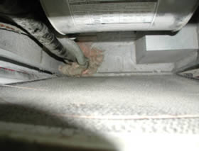
- Rodent
damage in belly (previously noted by homeowner)
- West
end wall of master bathroom with possible moisture
problem.
TESTING
Duct
test
A
duct system airtightness test was also completed. A
duct tester was attached to the air handler unit. The
supply registers were temporarily sealed off and the
system was then depressurized to 25 pascals. The
total and outside leakage flow components were measured. An
airtight duct system would have zero leakage or both
the CFM25total and CFM25out would
be 0.
Duct
System Airtightness |
CFM25total =
148 |
Pressure
diagnostic testing
Pressure
differential measurements were completed to determine
a magnitude and direction of flow across the envelope
when the air handler fan operates. Interior door
closure effect was also measured when the air handler
fan operated.
Pressure
Diagnostics w/ AHU
(Note:
the winds were calm)
|
Condition |
Pressure
differential (main wrt outside) |
All
fans off |
0
pa |
AHU
on |
-1.6
pa |
AHU
on & master suite door closed |
-10.7
pa |
AHU
on & all interior doors closed |
-13.0
pa |
The
pressure difference was also measured across each closed
door when the air handler fan was operating (all supply
registers were open and exhaust was off).
Pressure
across closed doors |
Pressure
differential (room wrt main) |
Master
bedroom |
24.5
pa |
Center
Bedroom |
3.9
pa |
End
Bedroom |
6.6
pa |
EFFECTS
- Return
air path to AHU is hindered when bedroom doors are closed – especially
the master suite door.
- Flow
imbalances cause the master bedroom to be overcooled
before the other bedrooms are cooled. This overcooling
causes the exterior vinyl covered walls to drop to the
ambient air dewpoint temperature or below.
- Duct
leakage, on the supply side, causes the entire building
to operate at a negative pressure. Any pathway
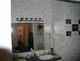
from the exterior to the interior – such as electrical
penetrations- provides a pathway for ambient air to reach
interior surfaces. One such area is at the light
fixture mounted on the wall of the master bath.
RECOMMENDATIONS
- Keep
thermostat set at 78 F or above.
- The
flow imbalances (especially the excessive air in the
master suite) should be corrected.
- All
duct leaks should be repaired with mastic. The
supply plenum and all risers should be checked and repaired
as needed. The refrigerant line penetration through
the air handler cabinet should also be sealed. The
duct leakage should not exceed 3% of floor area or CFM25
less than 40.
- The
3-inch reducer in the supply plenum should be removed.
- A
separate return direct to the AHU is needed (through
the wall or jump duct) from the master suite.
- Sufficient
return air pathways should be installed in the rest of
the bedrooms.
- All
belly penetrations should be sealed with a permanent,
long-lasting seal. No duct tape.
- In
general, vinyl covered exterior drywall should not be
used in hot and humid climates.
HOUSE
2
DESCRIPTION
- 1368
Sq Ft
- Continuous
crawlspace with vented skirting
- Attic
flex duct system.
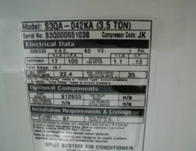
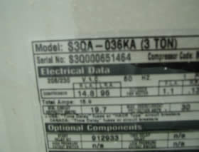
- 3.5-ton
A/C compressor – 3 row indoor coil
OBSERVATIONS
- Thermostat
was set at 76F
- Homeowner
reports that house has a very quick cool down.
- Pink
spotting” noted in center and end bedrooms. Appears
to be in path of supply air register throw. Moisture
content measured with a moisture meter appear normal.
- Possible
water damaged in hallway due to roof flashing leak at
exhaust fan.
- Airflows
were measured from each supply register – very
close to design flows.
TESTING
Blower
door test
A
blower door test was done to determine the airtightness
of the building envelope. A series of building
pressures and associated airflows was recorded. This
provides the necessary inputs to determine the CFM50
of the house.
Blower
Door Test
CFM50
= 808
[C=77.5,
n=0.60, r=0.989] |
The
values of C and n can be used as inputs for the house
airflow equation, Q=C* Pn . Thus,
for any given pressure difference, P, the airflow
crossing the building’s envelope can be determined.
Duct
test
A
duct system airtightness test was also completed. A
duct tester was attached to the air handler unit. The
supply registers were temporarily sealed off and the
system was then depressurized to 25 pascals. The
total and outside leakage flow components were measured. An
airtight duct system would have zero leakage or both
the CFM25total and CFMout would
be 0.
Duct
System Airtightness |
CFM25total =
46 |
Pressure
diagnostic testing
Pressure
differential measurements were completed to determine
a magnitude and direction of flow across the envelope
when the air handler fan operates. Interior door
closure effect was also measured when the air handler
fan operated.
Pressure
Diagnostics w/ AHU
(Note:
the winds were slight) |
Condition |
Pressure
differential (main wrt outside) |
All
fans off |
0
pa |
AHU
on |
0
pa |
AHU
on & master suite door closed |
0
pa |
AHU
on & all interior doors closed |
0
pa |
The
pressure difference was also measured across each closed
door when the air handler fan was operating (all supply
registers were open and exhaust was off).
Pressure
across closed doors |
Pressure
differential (room wrt main) |
Master
bedroom |
1.0
pa |
Center
Bedroom |
1.0
pa |
End
Bedroom |
1.0
pa |
Airflow
testing
The
duct tester may also be used as a powered flow hood. The
flow from each supply register was measured and compared
to the as designed airflows
Air
Flow At Supply Registers
(Measured
and Design CFM) |
Location |
Designed |
Measured |
Variance |
Master
Bath |
90 |
96 |
107% |
Master
Bed |
178 |
161 |
90% |
Kitchen |
78 |
118 |
151% |
Dining
Room |
186 |
180 |
97% |
LivingRoom1 |
106 |
130 |
123% |
LivingRoom2 |
106 |
117 |
110% |
Bed
1 |
103 |
112 |
109% |
Bed
2 |
161 |
140 |
87% |
Hall
Bath |
44 |
75 |
170% |
EFFECTS
- It
appears that the duct system leakage, return air pathways
and airflows to various zones is within acceptable limits.
- The
air conditioning system appears to be oversized which
allows for the rapid cool down of the home that homeowner
commented on. This leads to short cycling of the
compressor and inadequate runtime of the system to provide
dehumidification. The higher interior humidity
level causes the occupant to lower the thermostat seeking
cooling comfort.
- The
supply registers in the bedrooms with the “pink” spotting
are blowing cooled air out the exterior vinyl covered
gypsum. This “washing” of the wall
by the cool supply air will tend to lower its temperature – more
than likely below the exterior dewpoint.
- The
wall construction may allow for the intrusion of liquid
water. Though the design appears to be an approved
technique, there is a lack of a continuous drainage system. This
may allow water to enter the wall cavity in a liquid
form and be trapped.
RECOMMENDATIONS
- Keep
thermostat set at 78 F or above.
- The
supply registers in the bedrooms should be redirected
as to prevent “washing” of the exterior
walls.
- The
exterior wall design should be invested. The
manufacturer of the siding product should be called
in to assist in the investigation and offer their
expertise.
- Proper
sizing of the air conditioning system is important
when it is to used in a hot humid climate. Or
a stand alone dehumidification system should be employed.
- In
general, vinyl covered exterior drywall should not
be used in hot and humid climates.
HOUSE
3
DESCRIPTION
- 1368
Sq Ft
- Continuous
crawlspace with vented skirting Attic flex duct system.
- 3.5-ton
A/C compressor – 3 row indoor coil
OBSERVATIONS
- Thermostat
was set at 76F
- Homeowner
reports that house has a very quick cool down.
- “Pink
spotting” noted in center and end bedrooms. Appears
to be in path of supply air register throw. Moisture
content measured with a moisture meter appear normal.
- Possible
water damaged in hallway due to roof flashing leak at
exhaust fan.
- Airflows
were measured from each supply register – very
close to design flows.
TESTING
Blower
door test
A
blower door test was done to determine the airtightness
of the building envelope. A series of building
pressures and associated airflows was recorded. This
provides the necessary inputs to determine the CFM50
of the house.
Blower
Door Test
CFM50
= 808
[C=77.5,
n=0.60, r=0.989] |
The
values of C and n can be used as inputs for the house
airflow equation, Q=C* Pn . Thus, for
any given pressure difference, P, the airflow crossing
the building’s envelope can be determined.
Duct
test
A
duct system airtightness test was also completed. A
duct tester was attached to the air handler unit. The
supply registers were temporarily sealed off and the
system was then depressurized to 25 pascals. The
total and outside leakage flow components were measured. An
airtight duct system would have zero leakage or both
the CFM25total and CFM25out would
be 0.
Duct
System Airtightness |
CFM25total =
46 |
Pressure
diagnostic testing
Pressure
differential measurements were completed to determine
a magnitude and direction of flow across the envelope
when the air handler fan operates. Interior door
closure effect was also measured when the air handler
fan operated.
Pressure
Diagnostics w/ AHU
(Note:
the winds were slight) |
Condition |
Pressure
differential (main wrt outside) |
All
fans off |
0
pa |
AHU
on |
0
pa |
AHU
on & master suite door closed |
0
pa |
AHU
on & all interior doors closed |
0
pa |
The
pressure difference was also measured across each closed
door when the air handler fan was operating (all supply
registers were open and exhaust was off).
Pressure
across closed doors |
Pressure
differential (room wrt main) |
Master
bedroom |
1.0
pa |
Center
Bedroom |
1.0
pa |
End
Bedroom |
1.0
pa |
Airflow
testing
The
duct tester may also be used as a powered flow hood. The
flow from each supply register was measured and compared
to the as designed airflows
Air
Flow at Supply Registers
(Measured
and Design CFM) |
Location |
Designed |
Measured |
Variance |
Master
Bath |
90 |
96 |
107% |
Master
Bed |
178 |
161 |
90% |
Kitchen |
78 |
118 |
151% |
Dining
Room |
186 |
180 |
97% |
LivingRoom1 |
106 |
130 |
123% |
LivingRoom2 |
106 |
117 |
110% |
Bed
1 |
103 |
112 |
109% |
Bed
2 |
161 |
140 |
87% |
Hall
Bath |
44 |
75 |
170% |
EFFECTS
- It
appears that the duct system leakage, return air pathways
and airflows to various zones is within acceptable limits.
- The
air conditioning system appears to be oversized
which allows for the rapid cool down of the home that
homeowner commented on. This leads to short cycling of the
compressor and inadequate runtime of the system to provide
dehumidification. The higher interior humidity
level causes the occupant to lower the thermostat
seeking cooling comfort.
- The
supply registers in the bedrooms with the “pink” spotting
are blowing cooled air out the exterior vinyl covered
gypsum. This “washing” of the wall
by the cool supply air will tend to lower its temperature – more
than likely below the exterior dewpoint.
- The
wall construction may allow for the intrusion of
liquid water. Though the design appears to be an approved
technique, there is a lack of a continuous drainage system. This
may allow water to enter the wall cavity in a liquid
form and be trapped.
RECOMMENDATIONS
- Keep
thermostat set at 78EF or above.
- The
supply registers in the bedrooms should be redirected
as to prevent “washing” of the exterior walls.
- The
exterior wall design should be invested. The manufacturer
of the siding product should be called in to assist in
the investigation and offer their expertise.
- Proper
sizing of the air conditioning system is important when
it is to used in a hot humid climate. Or a stand
alone dehumidification system should be employed.
- In
general, vinyl covered exterior drywall should not be
used in hot and humid climates.
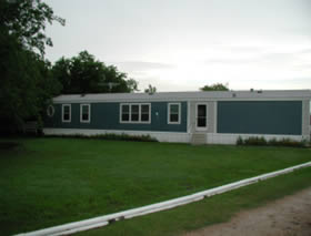
Pictures - House
1
|
|
Front
elevation |
Master
bath wall with moisture problem |

|
|
MS
bath plumbing penetration with what appears to
be evidence of rodent traffic. |
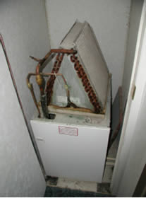
Air
handler unit located adjacent to master suite. |
|
Refrigerant
line penetration “sealed” with fiberglass
insulation. This is a direct leak path
to the floor cavity, which brings warm moisture
air from the crawlspace through the floor cavity
and into the conditioned air stream. |
House
2 |
|
|
|
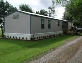
Exterior
elevation |
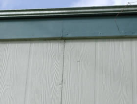
Siding
with obvious gap |
|
|
AC
nameplate |
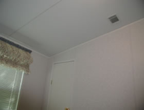
Supply
register in bedroom |
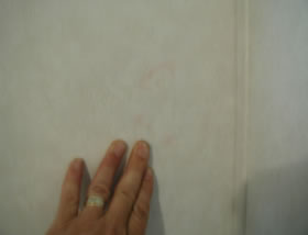
|
|
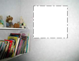
“Pink
spotting” in one of the bedrooms |
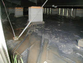
Ground
cover – typical |
House
3 |
|
|
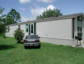
|
Exterior
elevation |
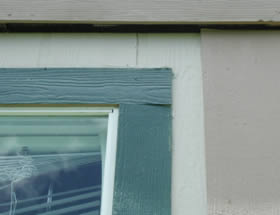
Siding
with obvious gap |
|
|
AC
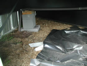
nameplate |
Wet
crawlspace with ground cover and venting |
 |
|
| Supply
register in bedroom blowing onto wall assembly. Pink
spotting noted in air pathway. |
|
|
Disclaimer:
This report was prepared as an account of work sponsored by an agency
of the United States government. Neither the United States government
nor any agency thereof, nor any of their employees, makes any
warranty, express or implied, or assumes any legal liability
or responsibility for the accuracy, completeness, or usefulness
of any information, apparatus, product, or process disclosed,
or represents that its use would not infringe privately owned
rights. Reference herein to any specific commercial product,
process, or service by trade name, trademark, manufacturer,
or otherwise does not necessarily constitute or imply its endorsement,
recommendation, or favoring by the United States government
or any agency thereof. The views and opinions of authors expressed
herein do not necessarily state or reflect those of the United
States government or any agency thereof.
|


