

Process and Energy Efficiency Review
for
Premier Building Systems
Kent, Washington
by
Florida Solar Energy Center
Dept. of Industrial Engineering
University of Central Florida
and
The Center for Housing Innovation
G. Z. Brown
Ron Kellet
Pete Haas
Janet McIlvaine
Michael Mullens
Phillip Read
Armin Rudd
Energy Efficient Industrialized Housing
May 6-7, 1992
ACKNOWLEDGEMENT
This research is funded by the U.S. Department of Energy, Office of Building Energy Research and Development; Mr. John Millhone, deputy assistant secretary; Mr. George James, program manager. We appreciate the cooperation of Premier Building Systems during our visit. We especially thank Mr. Ed Jones, general manager; Mr. Michael Wall, president; Mr. Mike McKenna, southwest regional manager; Mr. John Cancil, production and plant manager; Mr. Jerry King, quality control manager; Mr. Tim Costner, sales representative; and Mr. Kim Gwo P.E. for their hospitality and permission to widely disseminate this report.
FOR MORE INFORMATION CONTACT:
Subrato Chandra
Florida Solar Energy Center
300 state Road 401
Cape Canaveral, FL. 32920
Phone:407/783-0300, x 128
Fax:407/783-2571
EXECUTIVE SUMMARY
Background
The Energy Efficient Industrialized Housing (EEIH) project seeks to help industry increase the energy efficiency of its products and its productivity. Industry can take advantage of the EEIH project by participating in a short but intensive two-and-a-half-day PEER (Process and Energy Efficiency Review) visit.
Procedure
Between six and nine members of the EEIH project team visit the industrialized housing manufacturer. On the morning of the first day of the PEER visit there is an introductory briefing by the EEIH team and the housing manufacturer, followed by a plant tour. By early afternoon of the first day, the energy, manufacturing and design groups split up and begin work in their specific task areas. The energy group tests model homes for thermal insulation quality and building air leakage, using an infrared imaging system and a blower door. Special attention is paid to the air distribution system and its impact on energy efficiency, health, safety and durability. The manufacturing group evaluates areas such as labor productivity, materials handling, inventory management, manufacturing methods, and work-place safety. The design group performs an assessment of design and marketing methods. Day two is a continuation of work in the separate task areas. The PEER visit concludes on the third day after an exit briefing with the CEO and senior management. Recommendations are made and discussed in each of the energy, m manufacturing and design areas. A full report follows.
Company Profile
On May 6 and 7, 1992 a Process and Energy Efficiency Review (PEER) was conducted for Premier Building Systems located in Kent, Washington. Premier Building Systems (PBS) is a four year old subsidiary of Premier Industries. The largest of 35 partners in the American Foam Manufactures Corporation, PBS manufactures stress skin insulated core (SSIC) panels for residential and commercial buildings. Their sales region includes all of the area west of the Rocky Mountains.
Recommendations
Energy Area
Three houses were tested for Premier Building Systems which were constructed in part with SSIC panels produced at their Kent, Washington plant. All of the houses were well within the air tightness standard set by the Bonneville Power Administration's Long-term Super Good Cents program. That program requires no more than 7.0 air changes per hour at 50 Pascals pressure. The air leakage results showed that all three houses were better than manufactured and site-built control houses used in two California studies.
Under natural pressure conditions, it is recommended that houses have a ventilation rate between 0.35 and 0.5 air changes per hour to maintain indoor air quality. All of the houses tested for Premier had estimated natural air change rates below 0.35. Only one of these had a mechanical ventilation system. A heat recovery ventilation system should be considered for the two houses that do not have it, especially if any additional air tightening is done.
SSIC panel construction is expected to be more air tight than stick frame construction, with less on-site effort, due to far fewer joints in the building outer shell. Knowing this, foam core panel builders and manufactures should be more aware of ventilation requirements.
One indication of sufficient ventilation air is the level of CO2 in the air. CO2 levels were monitored for two of the houses while six to seven researchers and occupants were inside. Neither house had an excessive concentration of CO2.
Recommendations to further tighten the building envelope are given here but should only be considered if a mechanical ventilation system is used; they are as follows:
- Seal all electrical wiring, plumbing, and duct penetrations with a fire stopping foam sealant, such as Insta-FireSeal, Insta-Foam Products, Inc. or Fire Stop Sealant/Fire Stop Foam, DOW Corning Corp.;
- Seal the inside or outside wall panel skins to the sub floor with high quality caulk;
- Where recessed light fixtures are necessary, use sealed fixtures;
- Seal window nailing flanges to the wall panel skin with high quality caulk;
- Use seamless flue pipe and/or seal the pipe joints for air-tight wood burning stoves.
One house had a forced air duct system. The duct system itself was relatively air-tight, with less than 2% of the total house leakage being duct leakage. The inside to outside pressure balance was good as long as the interior doors remained open, however, large pressure imbalances were found when the interior doors were closed. This pressure imbalance would increase air infiltration when the system fan was on. It is recommended that:
- A separate return duct be provided for at least the master bedroom and other rooms where doors may be closed a significant amount of time; and
- Where separate returns are not provided, a return air vent should be installed through the wall from each room to the main body of the house. Note that acoustic isolation may be reduced.
Only one insulation defect was noted. Where a conventional truss roof met a SSIC panel wall, several hot spots indicated that either no insulation existed there or that the insulation was improperly placed (compressed or buckled) so as to lose its effectiveness. It is recommended that:
- Ceiling batt or blown-in insulation be installed so that it extends over the wall top plate without blocking off the soffit to ridge ventilation path and without buckling or compressing the insulation.
Manufacturing Area
Premier has two key manufacturing strengths. First, an inherently simple product and process result in enviable flexibility in equipment, layout, capital requirement and production capacity. Second, the teamwork and coordination of manufacturing personnel allow operations to move with impressive speed and quality. Together, these strengths serve as a strong foundation for the manufacturing operation.
There are significant opportunities to improve Premier's manufacturing operation. First, Premier should review and upgrade manufacturing process plans prepared by Engineering. Currently, engineering drawings released to the production floor are incomplete and hard to read.
Data obtained from a study of manufacturing labor utilization indicate that Premier personnel spend significantly greater time reviewing engineering drawings (and less time in value-added operations) than other housing manufacturers.
In the longer term Premier should procure and layout manufacturing facilities which support and enhance the Manufacturing function. Premier's manufacturing facility is not ideal for its function. It is much too large for current production levels, column spacings and doors are too small for larger panels and ramps must be negotiated as materials enter and leave the building. Future layouts should reflect Just In Time (JIT) concepts.
Finally, Premier should continue to emphasize work-place safety, particularly in material handling functions.
Design Area
Energy efficiency within marketing and design processes was the focus of the design portion of this PEER visit. Design review of a typical house was not conducted. A marketing process review examined the advertising, product literature and procedures used to attract customers and coordinate a sale for opportunities to improve customer interest in energy efficiency. A design process review examined design decision making steps, procedures, tools and techniques for opportunities to improve energy efficiency in the finished product.
Much of the quality and energy efficiency of an R-Control house resides outside factors and processes Premier directly specifies or controls. Envelope design characteristics such as configuration, orientation and glazing area, for example, are a part of the images and requirements each customer brings to a sale. These are however, influenced by the built examples and prior sales that customers often see and hear about. In construction, Premier directly controls only the panel material, while builders contractually independent of Premier control whole house design quality, envelope integrity and air tightness. As a consequence, Premier cannot obligate but only influence a customer, a builder, and in some instances a designer to energy efficient decisions and practices with advice and example.
Since many pursue R-Control for its energy efficiency, there is opportunity to make energy a more prominent feature in marketing, sales and design processes. To do so effectively, illustrative, tangible energy performance indicators must be developed for the early contacts between prospective customers and the company as well as to enhance the capabilities of designers and builders to use the product effectively.
- Produce a booklet called 'Tips for Saving Money and Improving Energy Performance with R-Control Construction' for typical client groups -- owner builders; architects / builders.
- To better compete with conventional framing on a cost and performance basis, produce a second booklet called 'Where R-Control Construction Offers Cost and Energy Advantages over Conventional Construction' for typical client groups -- owner builders; architects / builders.
- The warranty offered to customers is unique in the industry and presents an opportunity to differentiate R-Control construction from its competitors. Consider expanding the current component warranties to a whole building shell performance warranty when customers purchase wall, floor and roof components.
- Substantiate claims to better energy performance over conventional construction with field measurements and data.
- Since many customers come to Premier with an awareness of energy conservation with this product, leverage their interest toward higher performance goals and potentially larger sales.
- Develop and demonstrate strategies for builders to simplify and expedite field erection and improve quality processes where R-Control system is different or more costly than conventional construction.
- Document the significant bank of existing energy efficient design and construction experience with R-Control and use it in marketing.
-
1.1 Building Envelope Air Leakage
1.2 Forced Air Duct Leakage and House Pressure Balance
1.3 Insulation Quality
2.0 MANUFACTURING
3.0 DESIGN AREA
-
3.1 Description of Marketing, Sales, Design
and Engineering Processes
3.2 Identify Customer
3.3 Define Project
3.4 Describe Project
3.5 Manufacture the Project
3.6 Assemble the Project
3.7 Recommendations
1.0 ENERGY TESTING AREA
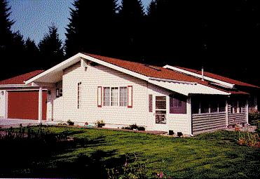
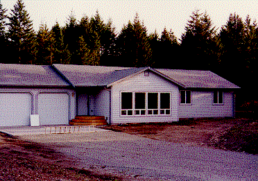
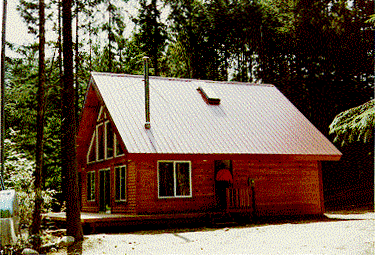
Three houses were tested for Premier Building Systems which were constructed in part with stress skin insulated core (SSIC) panels produced at the Kent, Washington plant. A brief description and photograph of the three houses follows:
-
House #1, Olympia, WA:
- SSIC panel walls and roof, conventional floor over crawl space;
- Occupied; 3 years old; 1850 ft2; 15,420 ft3;
- Zoned electric heat (no central ducting);
- Heat recovery ventilation system installed;
- One story; Normal exposure to wind; Small air leakage cracks;
- Double-glazed, extruded vinyl frame, slider windows
-
House #2, Rainier, WA:
- SSIC panel walls and floor (crawl space), conventional roof;
- Panel interior walls for bathroom and laundry for sound-proofing;
- Unoccupied; Less than 1 year old; 1550 ft2; 14,800 ft3;
- Central heating by electric furnace (single central return duct);
- No heat recovery ventilator;
- One story; More than normal exposure to wind; Normal air leakage cracks;
- Double-glazed, extruded vinyl frame, slider windows
-
House #3, Anderson Island, WA:
- SSIC panel walls and roof, conventional floor over crawl space;
- Unoccupied; Less than 1 year old; 1260 ft2; 12,180 ft3;
- Zoned electric heat (no central ducting);
- No heat recovery ventilator;
- One and one-half story; Normal exposure to wind; Small air leakage cracks.
- Double-glazed, extruded vinyl frame, slider windows
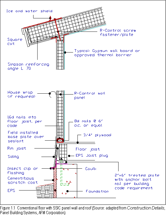
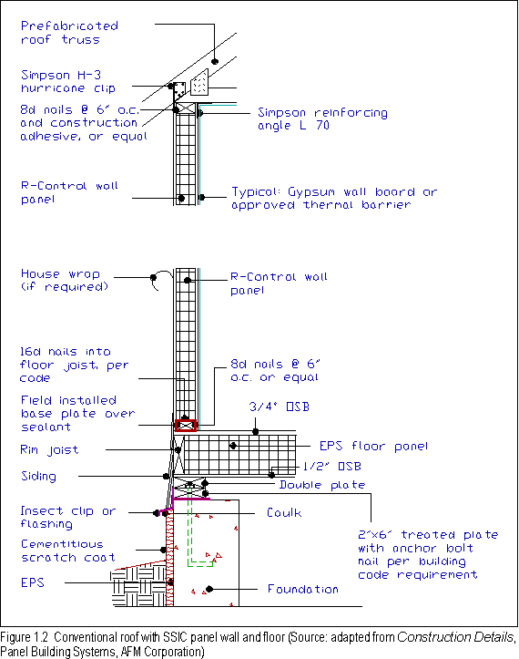
Figures 1.1 and 1.2 are section details showing the construction of (1.1) a SSIC panel wall and roof with a conventional floor and (1.2) a conventional roof with SSIC panel walls and floor. These two figures are included to acquaint the unfamiliar reader with the way SSIC panels are put together as floors, walls and roofs in combination with conventional framing components.
Air leakage through the building envelope was evaluated using a blower door. A multi-point de-pressurization test was conducted. Table 1 gives a summary of the blower door test results.
Table 1
Summary of Blower Door Test Results
| House #1 Olympia, WA |
House #2 Rainier, WA |
House #3 Anderson Island, WA |
|
| floor area (ft2) | 1,850 | 1,550 | 1,260 |
| volume (ft3) | 15,420 | 14,800 | 12,180 |
| ELA (in2) | 77 | 72 | 29 |
| EqLA (in2) | 143 | 137 | 56 |
| ACH50 (1/hr) | 5.2 | 5.4 | 2.8 |
| ACH50/20 (1/hr) | 0.26 | 0.27 | 0.14 |
| N | 25.90 | 16.65 | 27.97 |
| ACH50/N (1/hr) | 0.20 | 0.33 | 0.10 |
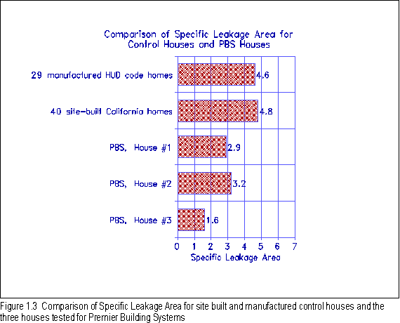
| SLA (ft2/ft2) | 2.9 | 3.2 | 1.6 |
The following provides a brief explanation of the terms in Table 1. ELA is the effective leak area that would exist at a house pressure of -4 Pa. EqLA is the equivalent leak area that would exist at a house pressure of -10 Pa. ACH50 is the air change rate at -50 Pa. ACH50 divided by 20 gives an uncorrected estimate of the natural air change rate as proposed by Persily. The factor N was developed by Sherman to correct for climate, building height, exposure to wind, and size of leak cracks. ACH50/N then gives a corrected estimate of the natural air change rate as proposed by Sherman. SLA is the specific leakage area, which normalizes the ELA by floor area. Recommended reading on this would be Infiltration: Just ACH50 Divided by 20? by Alan Meir, published in Energy Auditor & Retrofitter, July/August 1986 issue.
All three houses are relatively air-tight houses, with house #3 being exceptionally air-tight. They all performed to the Bonneville Power Administration's Long-term Super Good Cents standard for air tightness (7.0 ACH50). Figure 1.3 presents a comparison of the three houses tested for Premier Building Systems to other manufactured and site-built control houses on the basis of SLA. As shown, all three houses were better than manufactured and site-built control houses used in two California studies.
The American Society of Heating, Refrigerating and Ventilation recommends that houses with less than 0.35 air changes per hour, under natural pressure conditions, be ventilated by mechanical means to maintain indoor air quality. A conservative goal in energy efficient houses is to construct the building shell as tight as possible then mechanically ventilate all areas of the house at a known rate. This is better than relying on random cracks in the building shell, and unknown driving forces such as wind, stack, and pressure imbalances due to air handling and combustion equipment, to provide ventilation. With mechanical ventilation, heat recovery is also possible. Each of the three houses tested for Premier had estimated natural air change rates below 0.35 ACH. Only one of these had a mechanical ventilation system. A heat recovery ventilation system should be considered for the two houses that do not have it, especially if any additional air tightening is done.
SSIC panel construction is expected to be more air tight than stick frame construction, with less on-site effort, due to far fewer joints in the building outer shell. Knowing this, foam core panel builders and manufacturers should be more aware of ventilation requirements.
One indication of sufficient ventilation air is the level of CO2 in the air. CO2 levels were monitored for houses #1 and #3 while six to seven researchers and occupants were inside. Neither house had an excessive concentration of CO2. The starting level was about 500 ppm and the ending level was about 800 ppm for both houses. The recommended level is below 1000 ppm.
Another part of the building envelope air leakage diagnostic testing is to find air leakage pathways. This is done by pressurizing the building to about 15-20 Pa with the blower door and using a chemical smoke generator to pin point the leakage. The most significant building air leakage paths were as follows:
-
House #1
- between the wall panel base plate and the floor decking;
- between the vinyl window nailing flange and the wall panel skin;
- electrical chases extending through the top plate of the wall panel;
-
House #2
- through nine recessed light fixtures installed in a kitchen soffit that was connected to the conventional roof space;
- electrical penetrations through the top plate of interior frame walls and exterior panel walls into the conventional roof space;
- plumbing and supply duct penetrations through the panel floor into the crawl space, especially in the utility room;
-
House #3
- electrical penetrations through the bottom plate of the wall panel and into the crawl space;
- joint in the flue pipe of the airtight wood burning stove.
Recommendations to correct the air leakage paths described above should only be considered if a mechanical ventilation system is used; they are as follows:
- Seal all electrical wiring, plumbing, and duct penetrations with a fire stopping foam sealant, such as Insta-FireSeal, Insta-Foam Products, Inc. or Fire Stop Sealant/Fire Stop Foam, DOW Corning Corp.;
- Seal the inside or outside wall panel skins to the sub floor with high quality caulk;
- Where recessed light fixtures are necessary, use sealed fixtures;
- Seal window nailing flanges to the wall panel skin with high quality caulk;
- Use seamless flue pipe or seal the pipe joints for airtight wood burning stoves.
1.2 Forced Air Duct Leakage and House Pressure Balance
Since House #2 was the only one with a central duct system, the data discussed in this section is only applicable to that house. In order to get an estimate of the air leakage in the central duct system, two blower door tests were conducted. The first test included the ducts in the house system to obtain the total system air leakage. The second test excluded the ducts from the house system to obtain air leakage through the house envelope alone. By subtracting the two results, an estimate of the duct leakage alone was obtained. The ducts were excluded from the house by sealing off the supply and return grilles with paper and tape.
For House #2, air leakage in the duct system amounted to two percent of the total leakage. Two percent duct leakage is relatively small. Many new and old houses tested by the Florida Solar Energy Center show duct leakage between fifteen and thirty percent.
To ascertain the effect of air handling equipment and interior door closure on the pressure balance of the house, pressure differential measurements were taken with various arrangements of equipment operating and interior doors open or closed. In a "worst case" arrangement, with the furnace fan and bathroom and kitchen exhaust fans on, and the interior doors closed, the main body of the house was 8.5 Pa below the outdoors. That negative pressure differential would cause a natural draft combustion appliance to back draft if one was in that space.
With the same "worst case" arrangement, pressure differentials were measured between the interior rooms and the main body of the house where the central return duct was located. The three bedrooms were pressurized to between +8.5 Pa and +11.5 Pa with respect to the main body. Relative to the outdoors then, the main body was at -8.5 Pa while one bedroom was at +3 Pa. This pressure imbalance would significantly increase air exchange with the outdoors while the fans were running and the interior doors were closed.
With the furnace fan on and the exhaust fans off and all interior
doors open, there was no pressure difference inside to outside.
Since in this case, the pressure imbalance was mainly due to return
air restriction when the interior doors were closed, and not due
to duct leakage, it would be best to provide a separate return
for each room or at least provide a return air vent through the
wall from each room to the main body. It is usually impractical
to cut the bottom of the interior doors off high enough to provide
adequate return air flow area.
Table of Contents
The quality of the thermal insulation and its installation is evaluated using infrared scanning. The infrared scanner measures the temperature of a surface based on the amount of infrared energy that is emitted from the surface. Through the scanner, relative temperature differences can vividly show where there is more or less insulation in a building assembly, or where air leakage paths may be completely by-passing the insulation.
An initial infrared scan is conducted throughout the house to view the condition of the insulation. After the initial scan, the blower door is used to de-pressurize the house to -15 Pa in order to cause outdoor air to find leak paths to the inside. As outdoor air moves through the building envelope, the surfaces that come in contact with the air are either heated or cooled. As long as the temperature difference is large enough (>10oF), the infrared scanner will quickly show the change.
Due to an unusually warm three day period, the temperature differences between inside and outside were not great enough to see minor insulation defects or air leakage paths. The temperature differences ranged between -8oF and +8oF. All of the solid framing, used for joining panels, and for window cripples and headers, were visible in the infrared, but the temperature d ifferences were small and no air leak paths became evident.
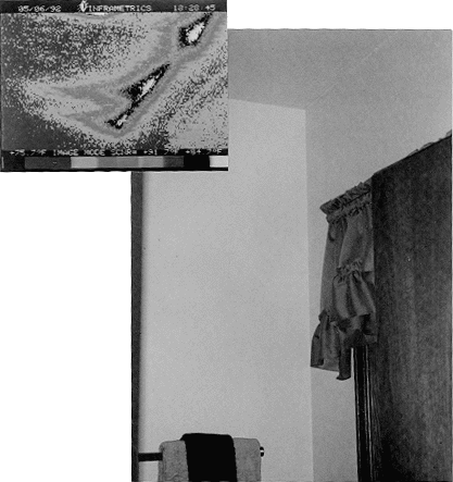
Only one insulation defect was noted. In House #1, all of the roof was constructed with SSIC panels except over a small bathroom where a conventional truss roof extended from the garage to form the ceiling of the bathroom. Where the truss roof met the panel wall, several hot spots indicated that either no insulation existed there or that the insulation was improperly placed (compressed or buckled) so as to lose its effectiveness. It was not possible to physically inspect that area from the attic. Figure 1.4 compares a photograph and an infrared image of the bathroom location where the insulation defect was found.
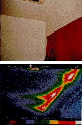
In order to maintain the continuity and effectiveness of the thermal barrier at the ceiling/wall connection, it is recommended that:
- Ceiling batt or blown-in insulation be installed so that it extends over the wall top plate without blocking off the soffit to ridge ventilation path and without buckling or compressing the insulation.
2.0 MANUFACTURING AREA
This section summarizes the findings from the manufacturing component
of the PEER review. Findings are based on a two day intensive
study of operations at Premier's Kent, Washington facility. The
study consisted of observing and videotaping operations at each
work station, discussing observations with production personnel
and reviewing process planning, inventory reports and other working
documents. Due to the limited information on which they are based,
recommendations should be viewed only as a starting point for
improving factory operations.
Table of Contents
To begin, it is important to identify Premier's key manufacturing strengths. These are the positive elements that clearly stood out during the study and that should be preserved and enhanced. The first is the inherent simplicity of the product and process. The result is an enviable flexibility in equipment, layout, capital requirement and production capacity. The simplicity also minimizes manufacturing inefficiencies and quality problems.
A second key manufacturing strength is the teamwork and coordination
demonstrated by Premier's manufacturing personnel. Teamwork demonstrated
during the laminating lay-up operation rivals that of Japanese
auto makers successfully executing a 6 minute stamping press die
change. The result is that, once started, these operations move
with impressive speed and quality.
Table of Contents
Several preliminary quantitative analyses were performed to develop a better understanding of Premier's manufacturing operation. They included an inventory analysis and a work sampling.
An analysis of Premier's inventory position was performed using data obtained from their computerized "Ending Inventory" report dated 5/6/92. Before using data from the report, sample inventory counts were made on the warehouse floor to verify report accuracy. Inventory levels were reported as shown in Table 3-1. Total inventory was reported to be $234,000 with $140,000 (60%) of this in finished goods (FG). Using the $1.8 Million annual panel sales figure reported by Premier, the FG inventory turns about 13 times per year. From a financial standpoint, this inventory turns rate is lower than necessary, indicating that Premier has invested more working capital in FG than is required. The immediate availability of raw materials and the relatively short production cycle time suggest that FG can be produced to order and very low FG inventory levels might be maintained. In fact, other panel manufacturers produce to order and hold only panels awaiting immediate shipment to customers. The relatively high FG inventory levels also had a negative impact on operations. This is discussed further in Section 3.3. Premier is very aware of the financial impact of the FG inventory levels and has chosen to build inventories during periods of low demand rather than lay off production personnel. However, given the negative operational impacts, Premier might consider using idle personnel time to perform non-production tasks such as team planning to address other opportunities identified in this report.
Table 2.1
Inventory
| MATERIALS | INVENTORY ($1,000s) |
| Finished Panels | 140 (60%) |
| Raw Materials | |
| OSB | 39 (17%) |
| Foam | 7 ( 2%) |
| Adhesive | 4 ( 1%) |
| Dim. Lumber | 11 ( 5%) |
| I-Beams/Headers | 11 ( 5%) |
| Other | 22 (10%) |
| Sub-Total | 94 (40%) |
| Total | 234 (100%) |
Work Sampling
A review of labor utilization for manufacturing personnel over the two day study period is shown in Table 3-2. Also shown are comparable data from other housing manufacturers. The data suggest potential improvement opportunities in the areas of performing operations (i.e., cut, lay-up, etc.), material handling and preparing to perform a task (primarily reading drawings). Specific opportunities are discussed in the following sections.
Table 2.2
Premier Work Sampling
| TASK | % OF TIME OBSERVED PREMIER |
% OTHER MFR. |
| Perform Operations | 23 | 40-50 |
| Transport Materials | 45 | 10-30 |
| Preparation | 32 | <10 |
2.3 Manufacturing Process Review
The following sections address findings by subject area.
Engineering
One of the greatest areas of opportunity for Premier's manufacturing operation is in the Engineering function. As indicated in the work sampling, 33% of personnel time is spent preparing to do work. This is primarily reading drawings and measuring. The study team observed an inordinate amount of time spent by the Manufacturing Manager translating incomplete, hard to read engineering drawings for his personnel. Personnel spent an equally inordinate amount of the ir time reviewing drawings, questioning design details/dimensions, asking for clarifications from the Manufacturing Manager and just translating what they needed to do based on the drawings received from Engineering. The result is a significant loss of time on the production floor, both for production personnel and management. Management time was almost completely consumed by this "on the floor" engineering.
The real opportunity is to provide manufacturing with information they can understand and trust, clear documentation describing exactly what is to be done. Only information which is needed to produce the product should be provided to the floor. This improved information from Engineering should result in both greatly improved manufacturing productivity. Perhaps more importantly, as the Manufacturing Manager is allowed to devote more time to managing (planning and controlling production, scheduling, QC, etc.) the production operation should run smoother with higher quality.
Facilities and Layout
Premier's manufacturing facility is not ideal for its function. It is much too large to support current production levels and may even be too large to support efficient manufacturing at double the current production level. Besides increasing overhead costs and decreasing profits, the problem with having too much floor space is that it tends to fill up. Premier is no exception. As indicated in the inventory analysis, FG inventory is higher than necessary. This not only has financial impacts, tying up scarce working capital, but also adversely impacts operations. FG and staged materials now tie up much of the available floor space, blocking access to materials and equipment and constraining routine material movement in the facility.
There are other problems with the existing facility. Building columns are on 20 foot centers in one direction. This becomes a problem when transporting and storing 24 foot panels. Ramps are not ideal for this operation. Fork trucks must go up and down ramps to receive most raw materials and ship completed panels. It would be better to have the operation at grade without ramps. To further complicate the ramp issue a relatively narrow ramp door is provided and materials must be maneuvered through it. The impact of these facility related problems is material handling inefficiency. Evidence of this inefficiency can be found in the work sampling data which indicates that 45% of personnel time is spent transporting materials. Most of these opportunities cannot be addressed in the current facility. However, as Premier builds or leases new facilities, they should keep these important facility features in mind, along with location, property value, etc.
Equipment and process layout is generally good with the exception of some cut-to-size finishing operations performed near the office area. Here, personnel set up make-shift cutting tables made from panel scraps. Not only are these operations relatively inefficient in themselves, they are often set up so that they and their staged materials block major access aisles, again constraining routine material movement and contributing to material handling inefficiency. These processes might be set up on a more permanent basis in a more appropriate area as inventory levels drop and floor space is freed.
On a broader scale, there are real opportunities for the introduction of Just In Time manufacturing principles into the Premier operation. First, manufacturing should be operated on a make to order basis. This will minimize, if not eliminate large volumes of finished panels. Second, the EPS cutting station might be linked directly to the glue roller in a Just In Time (JIT) type setup. In this scenario blocks might be fed directly from the last cutting operation to the glue roller, effectively eliminating the non-value added material handling steps of stacking blocks, moving stacked blocks to storage, storing, retrieving, moving to the glue roller station and unstacking blocks.
Methods and Equipment
In general, manufacturing methods and equipment were efficient and effective for their intended use. Some improvements might be considered. The existing EPS cutting operation should, at a minimum, be using a safer and more efficient hot-wire tool. The tool might have the following characteristics:
- Insulated handles
- Clamps or clips on the handles to facilitate setup
- Mounted on a shock cord over the table
Premier is investigating a mechanized EPS cutting table which utilizes a gantry mounted wire on a circular tool. The table appears to have promise for improving productivity, quality and safety and should be investigated further.
Several improvements are possible in the lay-up operation. Adhesive might be mixed in larger batches and fed to the roller using a hose. The lay-up jig currently requires personnel to climb to lay-up the topmost panels in a batch. The jig might be placed on a lift table so that components can be placed at a consistent level. The same approach might be used for handling EPS blocks at the EPS cutting station and the glue roller. If production levels were high enough, pick-and-place robots or automated stackers/destackers might be viable options for stacking and destacking sheet materials.
Opportunities also exist to upgrade processes and equipment in the cut-to-size finishing operations performed near the office area. Currently, personnel set up make-shift cutting tables made from panel scraps. They cut panels and I-beams using large circular saws and chain saws. Each time this area is set up it takes a major effort to marshall materials (for the table and staging platforms), equipment (circular saws, chain saws, hot wire cutting tools, extension cords, measuring tapes, etc.) and product (panels and I-beams). As an alternative, Premier might consider establishing a permanent cut-to-size cutting station utilizing a table saw, bridge mounted circular saw or router. This would minimize the extensive set-up times and make it much more efficient to offer value-added services.
Safety
Several observations suggest that Premier should continue to emphasize work-place safety. Personnel were observed riding on the raised forks of industrial forklift trucks. Personnel were using the truck as an elevator and then riding on the raised forks. During the ride, personnel would step from one fork to the other, handle lumber with one hand, etc.
Some amazing acrobatics were observed when feeding large EPS foam blocks into the glue roller. When pulling the top blocks from the stack, personnel would stand on top of the feed conveyor (gravity roller), pull the block from the top of the stack and jump off the feed conveyor as the EPS block falls onto the conveyor.
Finally, the jury rigged hot-wire handles (used as a temporary
measure) present potential hazards.
Table of Contents
Premier Building Systems supplies R-Control panels and accessories to commercial (35% of sales) and residential (65% of sales) contractors and builders in Washington, Oregon, California and Alaska and, to a lesser degree, in Arizona and New Mexico. The majority of Premier customers are owner / builders interested in energy conservation and open to innovative aspects of the product. Panels in quantities representing approximately 300 new houses a year are sold to owner builder customers (80%); developer customers (10%) and panel accounts (10%). This market includes additions and remodels as well as new construction.
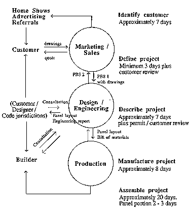
Principal characteristics of Marketing, Sales, Design and Engineering processes are illustrated for a residential sale of average complexity in Figure 3.1 and summarized in narrative below.
Premier products are marketed primarily through home shows and
print advertising. Of these, most prospective customer contacts
are made through home shows and referrals by word of mouth or
prior customers. Other prospective customers are identified through
referrals from Associated Foam Manufacturers (AFM), architects,
engineers and State energy commissions. Once identified, customers
move through sales, design and engineering, and production processes
with the assistance of Sales personnel.
Table of Contents
Prospective customers typically contact Premier with a house design defined or substantially defined. Many already have a quote in hand for conventional framing of roof, floors, walls and interior partitions. Sales personnel consult with the prospective customer to define project scope and parameters (PBS 1 form). Sales forwards customer drawings and project information to Design / engineering requesting a quote to supply panels to build the design. This quote is returned to sales for presentation to the customer.
Of the approximately 1500 prospective sales quoted annually by
Premier, roughly 300 or 20% ultimately become sales. Premier is
increasingly invited to quote on projects while the ratio of successful
sales to quotes has been diminishing. Each quote demands several
hours of sales, administrative, design and engineering personnel
time. Of quotes that are ultimately successful, relatively few
(15%) are accepted `as is'. Over half involve additional personnel
time in the form of `what-if' follow up questions and another
few (15%) are returned as incorrectly quoted.
Table of Contents
With customer acceptance of a quote, the project proceeds to design / engineering with payment of a deposit. From customer drawings, panel layout drawings are prepared on a CAD system (AutoCad.11). Design and panel layout drawings are given professional structural engineering review, returned to Design / engineering with calculations and an explanatory report for forwarding to the customer and permit submittal. Premier is experiencing delays at this engineering step causing disruption in the flow of projects through Design / engineering.
During the permit review period, design / engineering frequently responds to questions and requests from building code agencies and contractors. Often these discussions include evaluation of energy performance and building authorities may request design changes or detailed calculation of performance. A common energy related example is consultation regarding the area of glazing permitted based on envelope performance. Many customers also seek out prospective builders and contractors during this period and may consider or initiate other kinds of design changes as a consequence of these negotiations.
Once permits are secured and commitments negotiated with builders
and contractors, customers return approved drawings to Premier
and pay a manufacturing deposit to initiate production. From these,
Design / engineering prepares a final bill of materials and forwards
it to Production for scheduling.
Table of Contents
These processes are described in the manufacturing section of
this report. Typically, a residential project is 8 days in production.
Table of Contents
Typically, a residential project is 20 days in site construction.
Of these, roughly 2 - 3 are attributable to shell construction
in R-Control.
Table of Contents
3.7 Recommendations
- Although R-Control is an energy efficient and potentially economical product, whole house quality and performance depends on the capabilities of the designers and builders to use the product effectively. As less experienced designers and builders begin to use the product, examples of poor or inefficient designs and unrealized whole house performance attributable to poor installation practices may increase giving the product an undeserved negative reputation.
Produce a booklet called "Tips for Saving Money and Improving Energy Performance with R-Control Construction" for typical client groups -- owner builders; architects / builders.
Examples: What to do: Designing to modules for full panel utilization; roof pitches to use full panel lengths; using the `holes'; keys to field process savings. What not to do: Eliminating air paths; avoiding plumbing in exterior walls.
- To improve the opportunity for R-Control to compete with conventional framing, produce a second booklet called `Where R-Control Construction Offers Cost and Energy Advantages over Conventional Construction' for typical client groups - owner builders; architects / builders.
-
The warranty offered to customers is unique in the industry and presents an opportunity to differentiate R-Control construction from its competitors. Consider expanding the current component warranties to a whole building shell performance warranty when customers purchase wall, floor and roof components. Implications include expanded marketing of floor and roof systems, offering simulations of building performance, and developing quality control procedures for panel erection and envelope penetrations.
-
Despite claims to `not being in the design business', experience reveals that considerable personnel time can be allocated to advising customers, builders and regulatory agencies in matters of design. This service is an important part of gaining or keeping a customer and remaining competitive with other construction systems. The resulting revisions and redefinitions of a project become more difficult and disruptive as they are not now a part of the normal process of moving a project through the company. Many last minute changes and negotiations appear late in the process and interfere with the concentration and productivity of design, engineering and production personnel. Efficiency and productivity would improve if sales personnel solicited design changes when quote acceptance is returned to reduce later unplanned changes in engineering and production drawings.
-
Substantiate claims to better performance over conventional construction with data. For example, comparisons of conventional construction with R-Control construction are commonly based on similar code defined, theoretical, R-values for walls, floors and roofs. Components of similar R-values are by definition of similar thermal resistance and inconclusive comparators of energy performance. Field measures of air tightness, actual heat loss, or human comfort are more accurate and meaningful bases of comparison.
-
Provide prospective customers and builders with evidence that on a whole house, total project cost basis, R-Control can be more economical than conventional construction.
-
Since many customers come to Premier with an awareness of energy conservation with this product, leverage their interest toward higher performance goals and potentially larger sales. For example, the economic energy efficiency of R-control products ($ / unit R-value) improves with panel thickness. Sales of `higher than code performance', potentially more profitable, walls, floors and roof assemblies could result.
-
Develop and demonstrate strategies for builders to simplify and expedite field erection and improve quality processes where R-Control system is different or more costly than conventional construction.
-
Take advantage of a significant bank of existing energy efficient design and construction experience with R-Control. For example, create an R-Control client atlas referencing design, climate zone, R-value and annual heating bill to acquaint prospective customers and builders with examples of what has already been attempted and achieved.
Examples: Cathedral ceilings; skylights; light foundations etc. are features that can be more economically constructed in R-Control than conventional framing.
For example: Document field time and process advantages of R-Control over conventional construction to ascertain savings in productivity, construction loans and project overheads.
Example: An electrical service routing system to simplify wiring installation and maintain the thermal integrity of panels.
BAIHP Home | Overview | Case Studies | Current Data
Partners | Presentations | Publications | Researchers | Contact Us
Copyright © 2002 Florida Solar Energy Center. All Rights Reserved.
Please address questions and comments regarding this web page to BAIHP Master
