


III. BAIHP Research B
BAIHP continues to foster the research the implementation of the systems engineering approach with site builders which includes the incorporation of multiple concepts toward achieving the Building America program goals of saving 40% of total energy use while improving durability, indoor air quality, and comfort. Industry Partners in this area of BAIHP rise above “business as usual” production to strive toward this goal. BAIHP assists the builders, much as described in Section II, Technical Assistance, but goes on to instrument and collect relevant data from the house in an effort to validate the approach taken by the builder and add to our knowledge base of how to achieve the Building America goals.
BAIHP conducted research for site built housing which is reported in the following summaries:
Orlando, Florida
Category B: 2 houses
Research led by BAIHP Researcher Eric Martin
 |
Figure 82. The
Augusta, Cambridge Homes Building America Prototype. |
The partnership between BAIHP and production builder Cambridge Homes began late in 2001. Cambridge Homes had recently signed on with the EPA Energy Star Homes Program as a 100% Energy Star builder and expressed interest in increasing energy efficiency even further, as well as adding some “healthy home” features to their product. Also, Cambridge Homes expressed interest in BAIHP helping them design and build in a way that would prevent moisture related problems and call backs. BAIHP began by conducting analysis on several typical home designs and presenting results and strategies in a number of meetings with the builder. BAIHP also arranged a special meeting with the American Lung Association of Central Florida to discuss achieving the ALA Health House designation on the showcase model. However, the builder decided not to pursue the health house designation at that time.
To implement Building America strategies outlined by FSEC researchers, Cambridge Homes constructed a “prototype house” (Figure 82) to ensure that the strategies mate well with their current building practices (Table 60). A variety of home plans were reviewed to select an appropriate demonstration home, as well as a standard-practice counterpart. During construction, both homes were outfitted with dataloggers and associated monitoring equipment.
The homes were built in Baldwin Park, a new Orlando subdivision being developed on land that was once home to the Orlando Naval Training Center. The development will be 30% larger than New York’s Central Park, totaling approximately 1100 acres. Four hundred acres have been set aside for parks and open space, while 700 acres will be used for the construction of 3,000 homes, one million square feet of office space, and 200,000 square feet of retail space. Cambridge Homes is one of ten builders constructing homes in the community and plans to build 700 homes in Baldwin Park over the next five years.
Table 60. Cambridge Homes Specifications
| Component | Base Case (Covington) | Prototype (Augusta) |
| Conditioned Area | 2446 ft2 | 2672 ft2 |
| Envelope | ||
| Above-Grade Wall Structure | CMU first floor 2X4 Frame second floor |
Same |
| Above-Grade Wall Insulation | R-3.5 rigid foam R-13 Fiberglass Batt |
R-3.5 rigid foam R-13 |
| Above-Grade Wall Sheathing | OSB | Same |
| Attic | Vented r-30 batt | Unvented r-19 Icynene |
| Roof | Owens corning shingle | Elk architectural shingle |
| Windows | Single pane, clear Metal frame |
Double pane, low-e Metal frame |
| Infiltration (ACH50) | Not tested by FSEC | 3.0 |
| Equipment | ||
| # Of Systems | 2 | 1 |
| Heating | Heat pump HSPF = 8.65 | Same |
| Cooling | 2.5 ton, 13 SEER 2 ton, 13 SEER |
5 ton, 13 SEER |
| Thermostat | Programmable Standard |
Programmable |
| Ventilation | None | Thermastor Ultra-Aire |
| Water Heater | 50gallon Electric EF 0.88 | Same |
| Lighting | 10% fluorescent | 100% fluorescent |
| Appliances | Standard | Energy Star |
| Hers Score | 87 | 87.6 |
The demonstration home gave the builder firsthand experience with unfamiliar design elements, some of which have been incorporated into their standard practices. Such unfamiliar design elements included vapor permeable wall insulation, low-e windows, whole house dehumidifiers, unvented attics, and compact fluorescent lighting. FSEC researchers closely monitored the construction of the prototype and standard practice home, which was built to the Energy Star level. A duct test was performed in the prototype house during mechanical rough in to ensure leakage specs were met. Meetings also were held with the builder's HVAC contractor to discuss installation of the whole-house high efficiency dehumidification, filtration, and ventilation unit in the prototype model.
Upon completion of the home, duct testing was repeated to include inspection of the whole house dehumidification unit, and infrared camera analysis was conducted on the home. Data (Figures 83 and 84) collected from the two homes showed marked improvement in attic temperature (a primary cooling load) and indoor relative humidity control.
BAIHP performed training for Cambridge Homes' sales staff in March 2003. The training took place within the completed “prototype” model. Training focused on the advanced features of the Building America showcase model which Cambridge Homes began offering in April 2003.
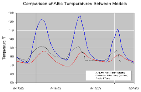
Figure 83. Comparison of attic temperatures
between Cambridge Homes
BA Prototype (Augusta) and Standard Cambridge
Homes construction (Covington).
Graph shows how sealed attic construction
in Augusta results in lower attic
temperatures than vented attic
construction during cooling season in Orlando, FL.
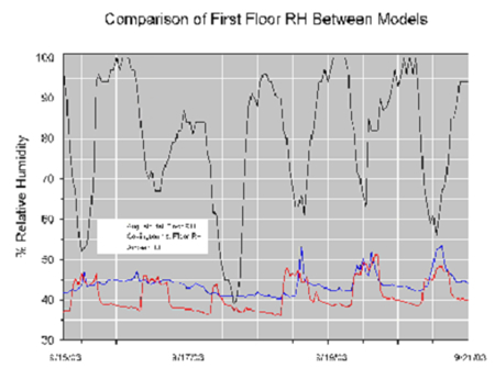
Figure 84. BA Prototype (Augusta)
contains whole house dehumidification system.
Plot shows daily
cycling of the system resulting in a lower relative humidity in
the prototype home than in the standard Cambridge Homes construction.
Late in 2003, Cambridge Homes began construction of a second home similar
to the “prototype” model, which was purchased by a customer
impressed with its attributes. FSEC staff conducted training for builder
and sales staff in December 2003 to review design methodologies and lessons
learned from the prototype model. A second meeting was held in January
2004 inspect progress of the home. Upon moving into the home, Cambridge
Homes reports that the new homeowner is extremely happy with the home.
To assist Cambridge Homes with reducing callbacks and moisture reduction
problems, FSEC researchers have also conducted “total” and
to “out” duct tests on six other Cambridge homes to determine
why the total duct leakage numbers were high (>10% of fan flow) despite
low to “out” duct leakage. “Out” is defined as
outside the conditioned space, including buffer spaces like an attic
or garage. Consistent leakage was found around the boot to register grill
connections. FSEC worked with Cambridge Homes and their HVAC contractor,
DEL-AIR, to specify air tight register grills.
In May 2004 additional instrumentation was installed in the prototype and base case homes to collect more detailed data on the different attic designs of the two instrumented homes (un-vented vs. vented). Data collection continued until October 2004.
Orlando, Florida
Technical Assistance by BAIHP Researchers Eric Martin and Neil Moyer
Rey Homes, a production builder in Orlando, in 2001 pledged to build a community of 200 homes that meet both Energy Star standards (HERS ‘99 score = 86) and the Florida Green Home Designation Standard. Rey’s partnership with FSEC began in October 2001 when researchers analyzed Rey’s standard home designs and construction and made recommendations for complying with these standards.
In the fourth budget period, Rey built 2 homes in their Villa Sol community for side by side comparison of unvented attic construction, a BAIHP recommended strategy. FSEC installed monitoring equipment in both homes, one with an unvented attic and one with a standard vented attic including a set of moisture pins in each house to monitor the moisture content of roof trusses in addition to the usual complement of temperature, humidity, and energy use meters. Instrumentation was complete early in the fifth budget period; however, data collection was not successful due to equipment and site complications. Monitoring equipment was removed during the sixth budget period and relocated to an active monitoring project.
Sharpless
Construction, Hoak Residence Energy and Moisture Studies
Longwood, Florida
Category A
Technical Assistance led by BAIHP Researchers Subrato Chandra and Dave
Chasar
Reports: Case Study
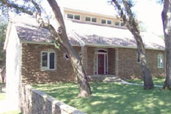 |
Figure 83. Hoak residence in
Longwood, Florida. |
This three-story, 4,250 square foot home was completed in February 2001 by Mr. David Hoak and Sharpless Construction in Longwood, Florida near Orlando. (Figure83) FSEC assisted the owner and builder by recommending a package of features that produced an exceptionally energy efficient design at a reasonable cost. Because the building envelope design and mechanical equipment selection work together as a system, the home can be cooled with a much smaller air conditioner than is needed by most homes of this size in this climate.
Envelope Features:
High Performance Windows
Roughly 25% of the annual cooling load in a typical Central Florida home is introduced through the windows. Recent advances in window technology allow this load to be greatly reduced. The windows in this residence are particularly useful in Florida because they have a very low Solar Heat Gain Coefficient (SHGC) to reduce direct solar gains, and a relatively high Visible Transmittance (VT) for natural daylighting.
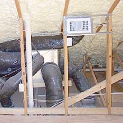 |
Figure 84. Semi-conditioned
space for the ductwork. |
Unvented Attic
Most Florida homes have vented attics with batt or blown insulation applied just above the ceiling. This exposes the air conditioning ductwork to very high temperatures and magnifies duct leakage problems. Sealing the attic envelope and insulating at the roof deck, as shown in Figure 84, provided a semi-conditioned space for the ductwork. This reduced conductive heat gain and minimized the detrimental impact of duct leakage.
Expanding Foam Insulation
A layer of expanding foam insulation (Figure 84) was applied to the underside of the roof deck to create an unvented, semi-conditioned attic (R-22). The same insulation was applied to all above-grade walls (R-11). While the insulation R-values were standard, the foam created a nearly airtight seal and greatly reduced outside air infiltration.
Continuous Air Barrier
Infiltration of Florida’s hot and humid outside air can have a big impact on energy use, building durability, and occupant health. The continuous air barrier, placed toward the outside of the building envelope, reduces this infiltration. Indoor air quality concerns were addressed by installing an energy recovery ventilator to introduce outside air.
The air barrier consists of a tightly taped housewrap installed over the exterior sheathing on all above-grade frame walls, and extruded polyurethane foam boards glued to the interior of the below-grade block walls. Expanding foam insulation provided an extra measure of air tightness at all above-grade exterior surfaces including the roof deck. Special care was taken to seal wall details such as corners, floor interfaces, and the roof junction. Blower door performance tests verified the home’s level of air tightness (ACH50 = 2.0).
Equipment Features:
2-Speed, Zoned Heat Pump
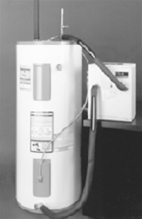 |
Figure 85. Heat pump water
heater. |
The building envelope design features described above greatly reduced the required air conditioner size. Manual-J HVAC equipment-sizing calculations showed the need for only 2½ tons of heating and cooling capacity. In this case the owner opted for a two-speed compressor, which provides either 2½ or 5 tons of cooling or heating depending on the need.
The Hoak home air conditioning unit typically operated in the 2½-ton mode until the late afternoon when it switched to the 5-ton mode for a few brief periods. In this home, energy use stays low because the low compressor speed operates the majority of the time. But, when quick cool-down or excessive loads require more capacity, the high speed compressor can meet the need.
Measured data indicated that the 5-ton mode operated about one in every four days during the three hottest summer months (June to August), usually for periods of 15 minutes or less. Even these short periods of high-speed compressor operation might have been avoided with proper use of a programmable thermostat. These results verify the Manual J sizing calculations and indicate that if a single speed HVAC system were installed, the optimum size would be 2½ to 3 tons.
Variable-speed Air Handler
Two benefits of using a variable-speed motor for air distribution are better moisture removal and energy efficiency. During the cooling season, slower airflow across a cold coil allows for more moisture removal. Wintertime comfort also is enhanced with this operation, since the coil has more time to warm before the air is brought to full flow.
Indoor relative humidity tends to increase during the fall and winter months when air conditioning activity declines. Without a dedicated dehumidifier, the air conditioner is the only means of reducing indoor relative humidity. When there is a call for cooling - the low-speed compressor in a variable speed system operates more consistently than a larger system and keeps relative humidity from rising to unhealthy levels.
Heat Pump Water Heater
Solar water heating would have been the first choice for this home, but poor orientation and too many shade trees forced a search for other options. (Figure 83) Natural gas also was unavailable in the area. To avoid the inefficiency of electric resistance water heating, a 6,000 BTU/hour heat pump water heater (Figure 85). Heat pump water heater produced all the hot water needs for a four-person household from April to September.
The water heater was connected to a standard 80-gallon electric water heater. By locating the heat pump inside the home, homeowners gained a summertime benefit of additional cooling and year ‘round dehumidification because the system removes moisture each time it operates.
Energy Recovery Ventilator
The energy recovery ventilator acts as a conduit to flush out stale indoor air and replace it with outdoor air. As the indoor air is expelled, a heat exchanger recovers up to 80% of the energy used to heat or cool the air and transfers it to the incoming air stream. This unit also transfers a portion of the moisture between the airstreams, which is useful during periods of high outdoor humidity.
Airtight Ducts
Attic and duct heat gain contribute to about 22% of the cooling needs of a typical Central Florida home when are ducts located in a vented attic above the insulation. While some home efficiency is lost by direct heat-gain through the duct insulation, a great deal more efficiency can be lost from unintended duct leakage from the ductwork into the vented attic. Duct leakage test results showed only 50 CFM of air was lost at 25 Pa of pressure differential in the Hoak residence. This leakage equates to 1.2% leakage per square foot of conditioned floor area - far below the leakage normally found in new Florida homes.
Energy Monitoring:
Monitors on the Hoak residence include 11 attic temperature and relative humidity sensors, three indoor sensors, a Hobo event logger to record the dehumidifier cycling time, and a tipping bucket rain gauge with Hobo logger to monitor the combined condensate of the air conditioner, dehumidifier, and heat pump water heater. In 2002, Alten Design also assembled a new logger monitoring computer with the capability of reading data from two Campbell 21X loggers. This computer was configured with remote monitoring and control capacity so that Partners can program and maintain the system without traveling to the site.
Findings
Duct Leakage
Duct leakage test results showed the Hoak home air loss was only 50 CFM at 25 Pa or 1.2% leakage per square foot of conditioned floor area – far below the amount of leakage normally found in new Florida homes.
Total duct leakage is less than 10% of air handler flow (200 CFM). Blower door performance tests verified the home’s level of air tightness at two air changes per hour at 50 Pa (ACH50 = 2.0). When including leakage around the supply grills, house leakage increased about 30%. Slightly more than half of the house leakage (1479 CFM at 50 Pa) is located in the sealed attic space (760 CFM at 50 Pa).
Cooling Energy
Initial data comparisons were made against data collected from a Lakeland, Florida residence (PVRes), designed by FSEC and monitored for more than a year. The PVRes home contained the most energy-efficient provisions researchers could devise, including a 5 kW photovoltaic system. Data collected at the Hoak home shows the cooling energy is nearly on par with the PVRes Home on a per square foot basis.
Envelope
Weekly data logs of the Hoak home provided by Alten Design from the 14 Hobo temperature and relative humidity sensors and pressure tests through March 2003, confirm that air pathways between the unvented attic and outdoors still exist. Researchers suspect that these pathways may be the primary source of moisture intrusion into the unvented attic space. Several whole house pressure tests (smoke tests) were performed by Alten Design and FSEC to isolate these external sources of air infiltration. Identified leaks were sealed, though actions have shown some benefit moisture levels are still higher than desired.
In order to isolate areas of leakage, barriers will be placed in the house splitting the areas under test into easier to monitor individual zones.
New Features in 6th Budget Period
An EnergyViewer to monitor whole house power use and the ERV control was modified to respond in tandem with bathroom vents. The ERV runs for a 15 min period of time. Also, new anticipating thermostats by Honeywell were installed.
Final Year of the Project
Researchers are studying heat pump water heater performance in this home with alternating two week periods of conventional water heating and heat pump water heating.
Lenoir City, Tennessee
Category A
Research by ORNL with BAIHP Support
Paper: Christian, J.E., D. Beal, and P. Kerrigan (2004). “Towards Simple Affordable Zero Energy Houses.” Proceedings of Performance of Exterior Envelopes of Whole Buildings IX, Clearwater, Florida, December 5 –10, 2004
 |
| Figure 86. Local sponsors in front of 2nd ZEH built by Loudon County HFH in partnership with ORNL. FSEC provided monitoring for the 1st and 4th ZEHs |
In partnership with Oak Ridge, BAIHP has instrumented two a zero energy homes (ZEH) built by Loudon County (TN) HFH in partnership with Oak Ridge National Laboratory. (Figure 86) See description in the Technical Assistance section of this report under Habitat for Humanity, Tennessee, Loudon County.
Data is available on-line at www.baihp.org on the “Current Data” page. A paper on the study was presented at the Buildings IX conference by Jeff Christian (ORNL) and David Beal (BAIHP-FSEC).
Gainesville, Florida
In April and May of 2003, four of 111 newly built apartments at the Brookside Apartment Complex were evaluated for potential moisture problems. Characteristics of the four apartments are summarized in Table 61. The ventilation strategy introduced untempered outside air to the return side of a central air handler.
Table 61. Apartment Characteristics
Apt ID |
Floor |
Occupants |
RH Control |
Outside Air Flow |
Infiltration (ACH50) |
Thermostat Setting |
1 |
1st |
1 |
AC only |
25cfm |
2.8 |
Variable |
2 |
2nd |
2 |
AC only |
17cfm |
2.5 |
Variable |
3 |
2nd |
0 |
AC only |
27cfm |
3.2 |
76º |
4 |
1st |
0 |
AC only |
28cfm |
3.9 |
76º |
Sensors were installed in four apartments that monitored Temperature and RH in three locations: the air handler cabinet, the kitchen, and the master bedroom close (Table 62). The readings from Apartment 2 were within recommended guidelines in all living spaces monitored, with no changes recommended.
Table 62. Apartment Results
Kitchen |
MB Closet |
|||
Apt ID |
Temp Av. |
RH Av. |
Temp Av. |
RH Av. |
1 |
71.9º |
54.3% |
71.7º |
62.0% |
2 |
76.0º |
47.6% |
76.9 º |
53.5% |
3 |
Invalid
data (See Figure ) |
N/A |
N/A |
|
4 |
71.4º |
50.2 |
N/A |
N/A |
| Note: Data from the Air Handler sensors were similar for all four apartments (reflecting the extremes expected in this locations with RH as high as 90% and 100%), and was not pertinent to the living space temperature and RH. | ||||
The temperature in Apartment 1 was lower than Apartment 2, the other occupied unit. The readings were within the acceptable level for comfort and mold control, but because the air conditioner ran longer, it also had a longer period to remove moisture. Inspection found that the windows were opened about 1 1/2”. When the occupant (the maintenance man for the complex) was asked why, he indicated that it was being done for “health purposes”.
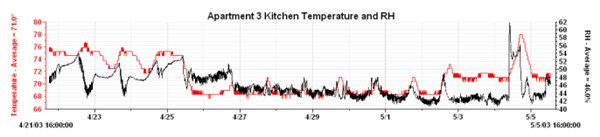
Figure 87. Apartment 3 Kitchen Temperature and RH
The remaining apartments testedvaried a large amount over the period
of test. Apartment 4 had wide swings in temperature readings.
With no significant period of time in which the temperature was stable,
it is assumed that the AC was not running properly in this unit.
Apartment 3 is notable because this unit was vacant and its temperature
should have stayed stable within three degrees. The good RH levels were likely
due to the longer Air Conditioner run times required to maintain the low temperature.
Outside Temperature and RH: The test period was during the beginning of Florida summer temperature and RH trends. Daytime high temperatures reach into the low 90’s with associated high RH levels in the afternoon. These cycles are reflected in the data collected, the most obvious of these being the Apartment 2 closet (Figure 88) where daily outdoor temperature peaks mimic those of the indoor temperature peaks.
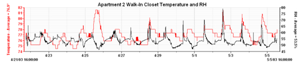
Figure 88. Apartment 2 Walk-In Closet Temperature and RH
Final observations: If all of the apartments have similar characteristics to those of Apartment 1 and Apartment 2, then no changes to lower interior RH levels are required at this time. RH level averages are well within the acceptable range – even in spaces where RH levels tend to get rather high (i.e. – closet) validating, at least preliminary the adequacy of the design principle of using outside ventilation air as has been implemented in these units.
Recommendations
-
Educate those involved in the care and maintenance of apartment complexes in basic principles of building science.
-
In future apartments locate a supply register in the closet to provide better humidity control for this area.
-
Check Apartment 3 & 4 equipment for proper operation, and calibration of thermostat.
Houston, Texas
BAIHP is assisting FAS and builder Joe Ecrette with envelope and mechanical system design on this home built with cementitious faced SIP panels. The home serves as a demonstration of an affordable, efficient home that is also well-suited for areas prone to seismic disturbance. A preliminary HERS ‘99 score of 89 is estimated.
BAIHP will provide data monitoring design assistance, equipment and installation to document energy savings. Data collection, processing and archiving will be provided through FSEC’s Infomonitors service, online at www.infomonitors.com.
Franklin, West Virginia
Radiant floor heating systems are becoming more common; however, there is little measured performance data documenting energy use and comfort indicators. Almost Heaven Habitat for Humanity in Franklin, West Virginia installs a slab mounted radiant floor system fed by a dedicated conventional, 80 gallon water heater. They have built approximately 15 houses with this system, designed from off the shelf components. In the final year of the project, BAIHP installed ground and slab instrumentation for radiant floor heating in Habitat house being constructed in West Virginia. Instrumentation so far consists of temperature probes embedded in the ground one and three meters from the slab, on the sides of the slab, and at three interior locations under and in the slab; the middle of the house, one meter from the edge of the slab, and in between these two locations. The house will be completed in the spring of 2007.
Central Florida area
 |
Figure 89. Hurricane
Jeanne at landfall (NOAA Satellite and Information Service
2004) |
-
Recent construction – homes receiving certificates of occupancy in 2001 and afterwards.
-
Stucco-clad masonry (1st floor) and frame (2nd floor) walls – the predominant building system in central Florida.
Several approaches were used to collect data:
-
An extensive literature search was performed in the areas of masonry walls, stucco finishes, cracks, and water intrusion.
-
Experts were interviewed to discuss findings and provide direction.
-
Homeowners were surveyed by telephone to learn more about their home and what they experienced during the storm.
-
Home inspections were performed to learn more about affected homes.
-
Selected elements of the construction process were observed to better understand workmanship issues.
-
Field tests were performed on new and existing homes to measure the extent of water intrusion due to wind driven rain.
Survey results indicate that 20% of all new homes built in central Florida in 2003 experienced water intrusion related to walls during Hurricane Jeanne. A survey of homeowners that reported water intrusion revealed that:
-
Although many builders experienced the problem, some builders were affected far more than their market share would suggest.
-
Single and two story homes were equally affected.
-
The vast majority of intrusion occurred on eastern walls, with some occurring on northeast and northern walls.
 |
Figure 90. Window corner crack |
A follow-up inspection of these homes found a variety of possible causes including: poorly sealed windows, unsealed wall penetrations (dryer vents, plumbing, electrical, rain gauge, etc.), poorly sealed expansion joints, and numerous cracks of varying shapes and sizes. Findings from an earlier inspection study confirmed the prevalence of these issues throughout the central Florida new home market. This earlier study found that 50% of homes between one and two years old had significant stair step cracking. (Figure 90)
On-site testing (Figure 91) was used to assess the relative importance of these factors. Testing of new homes (both under construction and occupied) revealed that stucco clad masonry walls without cracks did not leak, even without paint. Tests of homes that had leaked during Hurricane Jeanne demonstrated that cracks can facilitate water intrusion. Cracks did not need to be wide - cracks less than 0.39mm (1/64 inch) wide allowed water to penetrate the wall, run down and accumulate on the floor in one to two hours of simulated wind driven rain conditions. It is important to note that 57% of the cracks observed were wider than this, but could not be tested because they were not in a testable area of the house. It is also important to note that Hurricane Jeanne brought sustained winds of over 40 miles per hour with rain for a period of over 8 hours.
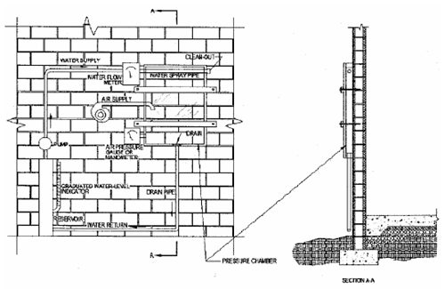
Figure 91. Schematic of test equipment and setup (ASTM 1604 – 04 2004)
Given the prevalence of stair step cracks in new central Florida homes
and their propensity to allow water intrusion, the remaining analysis
and recommendations focused on the cause, prevention and mitigation of
water intrusion through stair step cracks. The causes of the stair step
cracks observed are not obvious. No significant stair step cracks were
observed immediately after laying the block. However, after the cells
were grouted and the roof was installed, numerous stair step cracks were
visible. There were no discernable cracks in the footings related to
the stair step cracks observed in the walls. No problems with soil compaction
were found and the required rebar was installed in the footings. No significant
stair step cracks were observed immediately after stucco was applied.
However, within one year after the homes were completed, 50% exhibited
significant stair step cracking. The most likely cause of stair step
cracking cited in the literature is differential settlement. However,
the absence of discernible cracks in the footings casts some doubt on
this explanation as the sole cause. A more likely cause of many stair
step cracks is shrinkage. A common cause of shrinkage cracks in masonry
walls is using ‘wet’ or uncured concrete masonry units (blocks).
When uncured blocks are used to construct a masonry wall, they continue
to cure and experience a significant amount of shrinkage. Typical shrinkage
in a 50 foot masonry wall ranges from 3.1 to 6.9 mm.
Recommendations to homebuilders were made to reduce the incidence and magnitude
of water intrusion during hurricanes. Given the prevalence of stair step cracks
in new central Florida homes and their propensity to allow water intrusion, the
recommendations focus on the reduction of water intrusion through stair step
cracks. Several recommendations are also provided for homeowners. Recommendations
are provided at two levels. Level I recommendations should be implemented immediately.
They are believed to be low cost and high impact. Level II recommendations involve
substantive changes to the construction process and should be carefully evaluated
by each builder, possibly involving longer term testing.
Level I recommendations should be implemented immediately. They include:
-
Ensure proper support for footings by ensuring that site work for foundations meets code requirements as well as recommendations from the National Concrete Masonry Association.
-
Provide a step down ledge or seat for the concrete block approximately one inch below the slab to provide holding capacity for water that penetrates the exterior surface of the wall. Provide weep holes in the first course of block to allow this trapped water to escape.
-
Age concrete block 21 days before use to permit early shrinkage before walls are constructed.
-
Ensure that stucco is installed to ASTM standard C926 for 2 coat stucco. Curing times should allow the first coat to fully cure (some experts have suggested seven days), allowing the first coat to crack before the second coat is applied. The second coat should cure for 28 days before painting. The stucco should be reinforced with fibers to reduce cracking.
-
Use a premium, high build, acrylic coating that: meets Federal Specifications for resistance to wind driven rain (TT-C-555B), allows water vapor transmission permitting water to evaporate from the wall to the exterior, and provides high flexibility/elongation to cover existing and new cracks.
-
Near the end of the warranty period, repair all visible cracks with elastomeric sealant/patching compound and apply a second coat of paint.
Level II recommendations involve substantive changes to the construction process and should be carefully evaluated by each builder for impacts on market acceptance, cost, building system, and the construction process. They include:
-
Consider adding reinforcement to footings to lessen the effects of differential settlement on footings and thus reduce the incidence and severity of wall cracks.
-
Investigate and consider alternatives for floor/wall joint details that promote water entry into home.
-
Consider crack control strategies to address shrinkage: control joints and reinforcement to limit crack width. If walls are longer than 40 feet, control joints should be considered no further than 25 feet on center. Add joint reinforcement every other course to help hold cracks tightly together. Reinforcement (typically 9-gauge wire in either a “ladder” or “truss” configuration) is placed in bond beams, horizontal courses of U-shaped masonry block into which the reinforcing steel and grout is placed.
-
To better contain the water that does penetrate the exterior surface of the wall and direct it to the weep holes (see Level I recommendations), flashings should be considered at the base of the walls.
-
Alternative building systems such as cast-in-place concrete or pre-cast concrete panels may greatly reduce the risk of cracks and water intrusion associated with concrete masonry construction.
Energy Efficient Renovations of Storm Damaged Residences - Florida
Case Studies
Contract Report: Chasar,
Dave (P.E.), Neil Moyer, and Eric Martin. (2006) Energy Efficient Renovations
of Storm Damaged Residences - Florida Case Studies. FSEC-CR-1648-06. Florida
Solar Energy Center, Cocoa, Florida. September, 2006.
Storm-damaged homes offer the opportunity for repairs that reduce energy use, improve comfort and enhance resistance to future storms. Case studies of four Florida homes damaged in the summer of 2004 were documented to show the costs and benefits of various retrofit strategies. All four homes required roof replacement and each took advantage of roof cladding with higher reflectance than the original – a proven means of reducing cooling energy use. Two of the case studies included improvements to attic insulation, tightening of the envelope and/or duct system and improved efficiency equipment and lighting. Energy savings attributable to storm repairs were estimated through detailed computer simulation and in one case savings were directly measured in a before/after fashion.
Whole-home energy savings estimates derived by computer simulation ranged from a high 27%, in the home requiring the greatest amount of renovation, to a low of 1% in the home with a light colored shingle roof replacement. Cooling energy savings was also analyzed as it typically makes up the largest single subset of whole-home energy use in Central Florida. Cooling savings derived from the computer model ranged from 3% to 45% and, as in the case of whole home energy, was directly impacted by the level of home repair. Measured data obtained from one home showed a 19% reduction in cooling energy use after the dark shingle roof was replaced with white metal. This fell roughly in line with computer estimated cooling savings of 16%.
BAIHP Home | Overview | Case Studies | Current Data
Partners | Presentations | Publications | Researchers | Contact Us
Copyright © 2002 Florida Solar Energy Center. All Rights Reserved.
Please address questions and comments regarding this web page to BAIHP Master