


Published in the ASHRAE Transactions: Research,
Volume 99, Part 2, paper #3724. American Society
of Heating
Refrigeration and Air-Conditioning Engineers, Atlanta, GA, 1993.
Phase-Change Material Wallboard
for Distributed Thermal Storage in Buildings
Armin F. Rudd
ABSTRACT
Development and testing was conducted for a prototype phase-change material (PCM) wallboard to enhance the thermal energy storage capacity of buildings with particular interest in peak load shifting. Most importantly, it was determined that small scale differential scanning calorimetry can adequately predict (within 9%) the performance of PCM wallboard when installed in full-scale applications.
Initial PCM wallboard development tests were conducted on a small scale using a differential scanning calorimeter (DSC). The DSC measured the melting point and latent heat of selected phase-change materials, and of some prototype PCM wallboard. Based on these initial DSC tests, coconut fatty acid was selected for the room-scale PCM wallboard tests due to its favorable melting and freezing temperature range. At a loading of 25% by weight, the DSC measured an average latent heat of 9.57 Btu/lb (22.26 J/g) for the PCM wallboard. The average melting point was 76.8°F (24.9°C). Additional tests were conducted to ascertain DSC measurement reproducibility, spatial uniformity of PCM loading, and PCM high temperature stability.
Room-scale tests showed that the PCM wallboard had an average thermal storage capacity of 10.4 Btu/lb (24.2 J/g). This varied by only 8.7% compared to the latent heat recorded by the DSC. Thus, expensive, large-scale testing may not be required until a PCM wallboard product is well along in development.
The PCM wallboard development work, thus far, has experimentally shown that the concept is workable on a large scale, that phase-change material can be successfully integrated and distributed within a building with a significant thermal storage effect. However, to obtain the magnitude of storage required, more work is needed to identify or develop new materials with greater latent heat capacity while keeping the melting/freezing range between 72°F (22.2°C) and 79°F (26.1°C).
INTRODUCTION
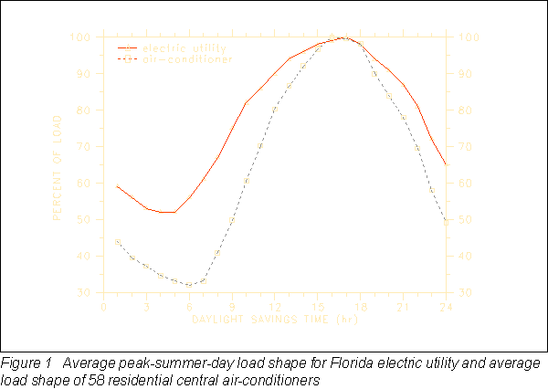
In many parts of the country, electric power utilities are finding that they cannot meet the summer peak electrical demand of their customers. Florida utilities in particular are faced with high growth rates; nearly every new house has central air-conditioning. For the largest power utility in Florida, the average peak-summer-day demand profile has nearly the same shape as the demand profile of a house's air conditioner for the same time period. Figure 1 shows the utility load shape (Taylor 1990) and the measured average load profile of 58 residential central air-conditioners (Paxon et al. 1980) in percent of load. The summertime peak generation load is between the hours of 12 noon and 9 PM. Most of the load comes from cooling equipment in buildings, and shifting much of it to off-peak periods would be advantageous. A building integrated and distributed thermal storage material such as PCM wallboard could shift most of the load coming from residential air conditioners from peak to off-peak time periods (Neeper 1990). As a result, capital investment in peak power generation equipment could be greatly reduced for some power utilities. These capital cost savings could be reflected in less expensive service to customers. Where power utilities are offering time-of-day rates, building integrated thermal storage could enable customers to take advantage of lower utility rates during off-peak hours. Building integrated thermal storage systems could also make conditions more favorable for the use of advanced solar cooling and heating technologies.
Energy storage materials need to be specifically designed for each climate to get maximum utilization during the dominant season of comfort conditioning energy use. For instance, in a cooling dominated climate, the summertime temperature in a house may be comfortable between 72°F (22.2°C) and 79°F (26.1°C), while in a heating dominated climate the wintertime indoor temperatures may range from 65°F (18.3°C) to 72°F (22.2°C). If a phase-change material is to be utilized efficiently, the melting/freezing range and the associated latent heat must be optimized.
Rather than develop a totally new wallboard product, this work focused on enhancing the thermal storage capacity of standard gypsum wallboard. The gypsum wallboard matrix makes an ideal supporting medium for the phase-change material since approximately 41% of the wallboard volume is air voids. Gypsum wallboard is commonly used in buildings throughout the nation and there is about 5000 ft2 (465 m2) of gypsum wallboard directly coupled to the conditioned air in an average 1500 ft2 (139 m2) house.
For a base case 1500 ft2 (139 m2) house on an average day during the peak month of July, in Miami, FL (Swami et al. 1989), the sensible cooling load between the on-peak hours of 12 noon and 9 PM totals to 87,976 Btu (92,797 kJ). Eighteen percent of that load could be stored by the standard gypsum wallboard if the room was allowed to cycle between 72°F (22.2°C) and 79°F (26.1°C). In order to defer all of the on-peak sensible load, 5.6 times the thermal storage potential of standard wallboard would be required.
Kamel et al. (1991) conducted an experimental study whereby thermal and moisture storage materials were placed in one of two side-by-side test rooms to demonstrate the effect of enthalpy storage on off-peak cooling in hot-humid climates. Thermal storage was added first by placing gallon water jugs on racks next to the walls. Moisture storage was added later by hanging panels of silica gel from the ceiling. The results demonstrated the need for moisture storage as well as thermal storage to maintain indoor comfort when using off-peak cooling.
Shapiro (1989a, 1989b) has shown several phase-change materials to be suitable for introduction into gypsum wallboard with possible thermal storage application for the Florida climate . These materials were mixtures of methyl-esters, methyl palmitate and methyl stearate, and mixtures of short-chain acids, capric and lauric acid. Although these materials had relatively high latent heat capacity, the temperature ranges required to achieve that thermal storage did not fall sufficiently within the range of comfort for buildings in hot climates. Hence, more work needed to be done to identify and test more suitable materials.
Suggested by Chandra (1989), and confirmed by a subsequent literature search, commercial coconut fatty acids had melting/freezing temperature ranges that were more suitable for our application than the previous materials tested by Shapiro. However, a lower latent heat was also expected due to a higher content of the unsaturated compounds of oleic and linoleic fatty acid.
RESULTS AND DISCUSSION
Differential scanning calorimeter tests on small samples
A differential scanning calorimeter (DSC) is an instrument that measures the heat capacity of small samples of materials. The sample holders for these tests are roughly 0.25 in (0.00635 m) in diameter and about the same dimension in height. For materials changing phase, the DSC gives the melting and freezing curves and the associated latent heats. The principle of operation is to keep temperature equilibrium between a test sample and a reference sample while the reference is being heated or cooled at a constant rate. The excess heat absorbed or emitted by the test sample is recorded as a function of time. Integration of these values gives an accurate measurement of the total heat of transition between two temperatures.
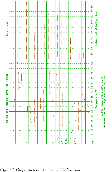
The initial phase-change material screening included a total of 36 DSC tests performed on three different groups of samples (Florida Institute of Technology, 1990): 1) pure samples of coconut fatty acids, short-chain acids and methyl-esters; 2) mixtures of short-chain acids (ratios given in Figure 3); and 3) wallboard samples infused with coconut fatty acids.
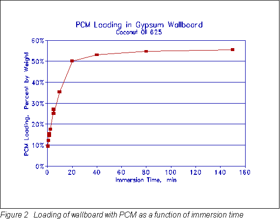
An apparatus was constructed to prepare the phase-change material (PCM) wallboard samples. This apparatus allowed 16 in. (.406 m) square pieces of gypsum wallboard to be immersed in a temperature controlled bath of the PCM. The temperature of the PCM was held at 104°F (40°C) to assure complete melting and to get quick penetration of the PCM into the air voids of the gypsum matrix. The immersion time was varied from 0.5 min to 240 min to obtain a relationship between PCM loading and immersion time. The amount of loading was important in order to maximize the useful amount of thermal storage without allowing weeping of excess PCM from the wallboard. A PCM loading of 25% by weight was chosen since tests showed that there was slight weeping of the PCM from the wallboard at higher loading. This agreed with previous work by Shapiro et al. (1987) although he used slightly higher loadings with other organic materials. To achieve the 25% by weight loading, the 0.5 in. (0.0127 m) thick gypsum wallboard was immersed in the 104°F (40°C) PCM for 5 min. The resulting product used 0.439 lbpcm/ft2 (2.14 kgpcm/m2). The cost of the PCM was $0.78/lb ($1.72/kg) or $0.34/ft2 ($3.66/m2).
Figure 2 gives a plot of PCM loading by weight as a function of immersion time for the coconut fatty acid 625.
To test the PCM wallboard in the DSC, small portions were cut from the 16 in. (.406 m) square boards. The samples did not include any paper from the front or back of the wallboard. Testing verified that the paper held very little PCM and should not be considered in the sample. Many tests were conducted on each PCM wallboard sample to assure good reproducibility of the results.
The DSC results for all of the 36 samples of the initial screening are organized graphically in Figure 3. Melting and freezing temperature ranges, melting and freezing points, and latent heats are given. Since the coconut fatty acid was only 25% by weight in the wallboard samples, the composite PCM wallboard has only a fraction of the latent heat capacity compared to the phase-change material alone. The 625 coconut fatty acid wallboard was selected for the room-scale tests since it was the only PCM wallboard whose melting and freezing points fell within the desired range of 71.6°F (22°C) and 78.8°F (26°C).
To verify the initial screening results for the 625 PCM wallboard, four additional samples were taken from both the center and edge portions of the PCM wallboard. Each sample was cycled in the DSC three times to determine the reproducibility of the test procedure and of the material response.
The average latent heat was 9.37 Btu/lb (21.80 J/g) for the center samples and 9.77 Btu/lb (22.72 J/g) for the edge samples. The average latent heat for all 625 PCM wallboard samples was 9.57 Btu/lb (22.26 J/g), with a standard deviation of 1.33 Btu/lb (3.09 J/g) or 13.9%. The edge samples were less repeatable than the center samples. The difference in latent heat of melting between the edge and center samples was 0.40 Btu/lb (0.92 J/g) or 4.1% of the average. This indicated that the outside edges absorbed and held slightly more PCM than the interior portions of the wallboard.
According to manufactures' literature, the boiling point of coconut fatty acid is 320°F (160°C) at 6 mm Hg pressure. Since the boiling point is high, it would be expected that the compound would be quite stable at temperatures well above room conditions. The sample was cycled in the DSC at 3.6°F/min (2°C/min) between 140°F (60°C) and 302°F (150°C) then subsequently re-tested within the normal temperature range. The thermal properties of the PCM wallboard showed no difference after the high temperature exposure.
Side-by-side room-scale tests
Two side-by-side test rooms were used for the full-scale PCM wallboard evaluation. For the sake of this discussion we will call them Cell B and Cell C. The rooms are 11 ft x 11 ft x 8 ft high (3.35 m x 3.35 m x 2.44 m) and are constructed alike. There is a common wall separating the two test rooms. The south walls have a room air conditioner and a window installed, the entrance doors are on the north walls. The east and west walls have no penetrations. A 1500-W portable electric resistance heater was placed in each room in the corner diagonally opposite the air conditioner. The air conditioners and heaters were computer controlled by digital and solid-state relays. In each room, a ceiling fan was operated continuously to keep the room air well mixed. The rooms were kept slightly pressured by forcing a measured amount of air into the room through a fan. This assured that the air infiltration rate was the same for each room.
A total of 61 channels of data were taken for each test room. Air temperature measurements were taken 1 ft (0.3 m) below the ceiling level, 1 ft (0.3 m) above the floor level, and in the middle of the room. The room dew point temperature was measured at the center of the room. The temperature of each wall, ceiling and floor surface was measured at several points. Electrical energy use (kwh) and power draw (kw) was measured for the air conditioner and the room equipment. Dew point and dry bulb temperature measurements were taken at the air conditioner supply and return locations. This allowed a calculation both sensible and latent heat transfer across the evaporator coil of the air conditioner. In addition, the air conditioner condensate was measured using a calibrated tipping bucket with a pulse output. The dry bulb temperature, dew point temperature, and mass flow rate of the infiltration air were measured to allow a calculation of the heat transfer by air infiltration. The mass flow rate of infiltration air was measured and calculated by the pressure differential across an orifice plate designed and machined according to the ASME standard for flow measurement (ASME 1984). Heat transfer by conduction through the walls, ceiling, and floor was measured directly by heat flux transducers. In addition to the measurements taken in the test rooms, 13 channels of environmental data were also recorded.
The room-scale testing was conducted in the summer of 1990. For any comparative test there must be an initial test to show that the control and the variable are initially the same. After all sensors were calibrated, and before PCM wallboard was installed, a null test was conducted for eight consecutive days. This test compared all energy flows for each room including: air infiltration; internal heat generation by equipment; heat removed by the air conditioner; heat convected to the walls, floor and ceiling; and heat conducted through the room envelope. It was determined that the rooms were thermally alike, within ± 7%, except for heat conduction through the exterior walls which is accounted for in the results.
After the null test, standard sheets of gypsum wallboard were weighed and selected to be within 2% of each other by weight. This gave assurance that all boards to be used had similar density. Seventeen of the 40 qualifying boards were installed in Cell B without any PCM treatment. The remaining 23 boards were cut in half and immersed in 625 coconut fatty acid PCM for 6 min (1 min longer than the small DSC samples, possibly because of less edge area or less permeable paper) to achieve a 25% by weight loading of PCM. Most of the infused wallboards had PCM loading values within 1% of the average. The same type of temperature controlled apparatus, constructed to make the small PCM wallboard samples for the DSC tests, was used to make the large 4 ft square (1.22 m) samples that were installed in Cell C.
Several room-scale tests were conducted with various control schemes, however, the test discussed here was conducted to gain a direct measurement of the energy stored in the PCM wallboard relative to the standard wallboard. The computer control was designed so that Cell C would cycle between 65°F (18.3°C) and 85°F (29.4°C) on a 24-hour basis and Cell B would be forced to follow the same temperature profile as Cell C. Because the same temperature conditions were maintained in each room, the difference in the measurement of the electrical energy use in each room directly gave the amount of additional energy that went into storage in the PCM wallboard (Cell C) relative to the standard wallboard (Cell B). Following this reasoning, it was named the "calorimeter-type" test. The temperature range of 65°F (18.3°C) to 85°F (29.4°C) is obviously outside the region of normal indoor comfort conditions, however, those temperatures were used for this experiment to compare the DSC results to the room-scale results.
Data analysis entailed the calculation of all heat transfer terms needed to complete an energy balance, first, on the room air, and second, on the wallboard. The measured data was recorded as 6 min averages or totals. All energy balance terms were summed for 12 hours which was 1/2 of the test cycle. The steady-state room air energy balance was:
-
where: Qinf = infiltration load
-
Qgen = internal heat generation
Qac = air conditioner load
Qwind = window conduction
Qdoor = door conduction
Qwb = heat convected to wallboard surfaces
Qair = thermal storage in room air
-
where: Qinf = infiltration
-
m = mass flow rate of air
hrm = enthalpy of room air
hamb = enthalpy of ambient air
n = number of time steps
The mass flow rate of air was calculated by measuring the pressure drop across an orifice plate in the infiltration air duct:
-
where: C = discharge coefficient
d = orifice diameter
ß = ratio of orifice diameter to pipe diameter
The enthalpy of the room and ambient air was calculated by ASHRAE psychrometric routines (ASHRAE Fundamentals, 1989) from the measured dry bulb and dew point temperatures. Internal heat generation was measured directly by a watt/watt-hr transducer. Energy removed by the vapor compression room air conditioner was calculated by:
where the return and supply air enthalpy was calculated from the respective dry bulb and dew point temperatures. The power draw and energy use of the air conditioner was also measured by a watt/watt-hr transducer. Heat conducted through the window was calculated by:
-
where: Uwindow = 0.9 Btu/hr-ft2-°F
(5.1 W/m2 °C)
Heat conducted through the door was calculated by:
-
where: Udoor = 0.077 Btu/hr ft2 °F
(0.437 W/m2 °C)
Thermal storage in the room air was small but was calculated anyway by:
-
where:
-
V = volume of air in room
cp = specific heat of air
Heat convected from the room air to the wallboard surfaces (walls, ceiling and floor) was given by subtraction after calculating all the other terms in the room air energy balance:
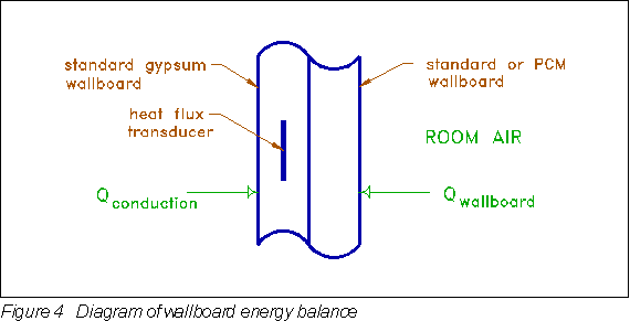
For the wallboard energy balance, heat conduction was directly measured by heat flux transducers embedded in the wallboard. Figure 4 depicts the wallboard energy balance. The difference between the heat conducted on one side and the heat convected on the other was equated to energy storage in the wallboard:
-
where: Qwbstor = thermal storage in the wallboard
-
Qcond = measured conduction at back of wallboard
The difference in wallboard storage between Cells B and C was equated to the energy stored in the PCM:
-
where: Qpcmstor = thermal storage in phase-change material
-
Qwbstor,c = wallboard storage, Cell C
Qwbstor,b = wallboard storage, Cell B
Data from 10 consecutive days of testing was analyzed. The ratio of PCM wallboard thermal storage to standard wallboard thermal storage was determined to be an average of 2.1. This was for a temperature change of 20°F (11.1°C), between 65°F (18.3°C) and 85°F (29.4°C).
The calculation of the thermal storage in the phase-change material was made in two ways. First, the difference in electrical heat generation required to keep both rooms at the same temperature should directly give the amount of energy that went into and out of storage in the PCM. However, this would only be true if all other loads were identical. As discussed earlier, the conduction loads through the walls, ceiling and floor were not the same for each cell. This was accounted for by adding the difference in conduction to the difference in generation to get the energy stored in the PCM as if the conduction loads were identical. This result agreed well with the second method in which the PCM thermal storage was calculated by calculating the wallboard energy balance for both rooms.
The bar chart in Figure 5 shows the energy balance terms. The infiltration, air conditioner, window and door loads were nearly the same for each of the side-by-side test cells. After the generation load was adjusted for the difference in conduction between the two cells, the difference in generation agreed closely (1.5%) with the difference in energy stored in the wallboard. Thus, the "calorimeter," in affect, balanced.
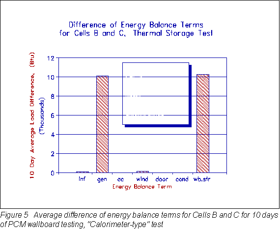
When the difference in thermal storage between Cell B and Cell C (which is the storage due to PCM only, not the gypsum) is divided by the total weight of PCM wallboard, then the latent heat of the PCM wallboard as measured in bulk by the room-scale test is given by:

This latent heat value of 10.4 Btu/lbpcmwb (24.2 J/gpcmwb) differs by only 8.7% compared to the 9.57 Btu/lbpcmwb (22.26 J/gpcmwb) recorded by the DSC. This indicated that small scale differential scanning calorimetry can adequately predict the performance of PCM wallboard when installed in full-scale applications.
To obtain the total amount of storage per unit area of PCM wallboard,
the thermal storage due to the specific heat of gypsum must be
added to the latent storage of the PCM. The storage by cp
![]() T is given by:
T is given by:

then the total storage per unit area is given by:

The result is 31.7 Btu/ft2 (360 KJ/m2). Keep in mind this is for a temperature change of 20°F (11.1°C), between 65°F (18.3°C) and 85°F (29.4°C), which is not realistic for indoor living conditions. For a more practical 7°F (3.9°C) temperature swing the thermal storage would be less.
Calculations by Neeper (1990) have shown that wallboard thermal storage capacity above 40 Btu/ft2 (454 KJ/m2) will probably be excessive for diurnal cycling. The useful storage is limited by low convection heat transfer coefficients between the room air and the wallboard surface. The result being that at higher capacities the PCM would not get fully charged or discharged during the period of one day.
Applications Problems Encountered
An offensive odor persisted in the wallboard and in the room air long after the wallboard had been infused with the phase-change material. Tests on samples showed that much of the odor was eliminated when the PCM wallboard was heated in an oven at 200°F (93.3°C) for several hours. The fatty acid components which contribute to the latent heat of fusion are stable, due to their high molecular weight and high boiling point. Thus, most of the volatile impurities can be removed at moderate temperatures as shown by the oven tests. The samples were weighed before and after being heated in the oven; the weight loss was less than 0.1%, however, a thin, greasy film was left inside the oven.
Another related problem was that many metal surfaces in the PCM wallboard test room, including copper and mill finish aluminum, developed a layer of corrosion due to the vaporization of impurities from the fatty acid. Surfaces that did not corrode, collected a thin, white layer of condensed material. Because of this problem, the copper/rhodium mirrors on the dew point temperature sensors were difficult to keep clean. It may be possible that the volatile impurities in the fatty acid could be vaporized before treating the wallboard.
Without the addition of fire retardants organic PCM's have unacceptable flammability characteristics for use on interior surfaces. Chemical fire retardants have been used successfully to reduce the flammability of PCM wallboard below that of plywood, but the latent heat capacity is reduced (Shapiro 1989b). Suggested by Chandra (1990), it may be economical to laminate a thin layer of untreated wallboard to the face of PCM wallboard to solve the flammability problem.
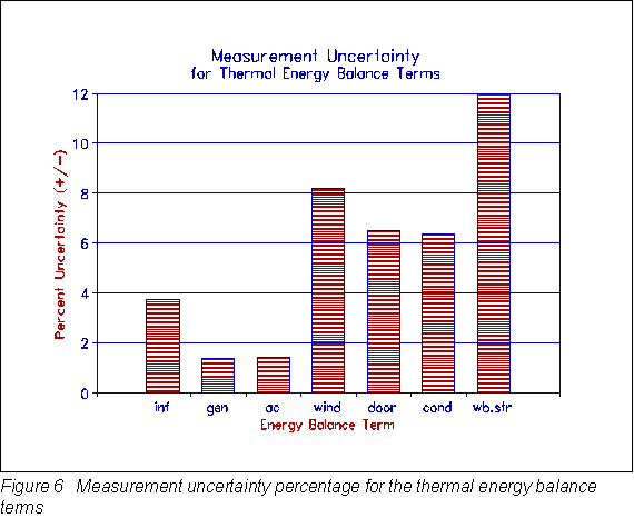
Measurement Uncertainty
A complete measurement uncertainty analysis was conducted according to the ANSI standard (ANSI 1985). The standard employs the root-sum-square method of combining random precision errors with fixed bias errors to obtain the uncertainty of a result. The result uncertainty can be described in absolute or percentage terms. Figure 6 gives a graphical view of the percent result uncertainty, at the 95% coverage level, for the most significant energy balance terms. Since the internal generation and air conditioner loads were relatively high and the watt-hr transducers are quite accurate, the percent uncertainty was relatively low. The ±12% uncertainty for the wallboard storage result was slightly higher than the target of ±10%, however, all of the uncertainties were within an acceptable range for the type of large-scale testing that was conducted.
CONCLUSIONS
Initial, small-scale tests, using a differential scanning calorimeter showed an average latent heat of 22.26 J/g (9.57 Btu/lb) at a PCM loading of 25% by weight. The average melting point was 76.8°F (24.9°C). Room-scale tests showed that the PCM wallboard had an average thermal storage capacity of 10.4 Btu/lb (24.2 J/g). This result varied by only 8.7% compared to the 9.57 Btu/lb (22.26 J/g) recorded by the DSC. This indicated that small scale differential scanning calorimetry can adequately predict the performance of PCM wallboard when installed in full-scale applications. Thus, expensive, large-scale testing may not be required until a PCM wallboard product is well along in development. The PCM wallboard had an average of 2.1 times more thermal heat storage capacity than standard wallboard over an 20°F (11.1°C) temperature change.
The PCM wallboard development work, thus far, has shown that the concept is workable on a large scale, that phase-change material can be successfully integrated and distributed within a building with a significant thermal storage effect. However, to obtain the magnitude of storage required, more work is needed to identify or develop new materials with greater latent heat capacity while keeping the melting/freezing range between 72°F (22.2°C) and 79°F (26.1°C).
FUTURE WORK
A longer-term goal of this preliminary research and development work is to develop an interior building skin material that can effectively store both thermal energy and moisture to provide better management of cooling loads for conditioned spaces. New work has begun to develop moisture storage coatings which may be applied to the PCM wallboard (Rudd 1992). Preliminary research involves the mixing of silica gel desiccant with latex paint and vinyl joint compound to create textured coatings for PCM wallboard. Another idea may yield a two-layer wallboard making a composite enthalpy storage wallboard. The back layer could be infused with PCM to provide thermal storage and the front layer incorporating desiccant to increase moisture storage and to reduce flammability (Chandra 1990). As moisture is adsorbed in the outer desiccant layer, the PCM layer will provide a sink for the heat of adsorption. As moisture is later desorbed from the desiccant layer, the wallboard will be cooled, removing energy from the PCM so that it may be heated again in the next cycle. This could work well with the off-peak cooling strategy since heat and moisture are simultaneously entering the room during peak periods, and heat and moisture are simultaneously being removed from the room during off-peak cooling periods.
ACKNOWLEDGEMENTS
Funding for this work was gratefully received from the Florida Power and Light Company and the U.S. Department of Energy. The author wishes to express his appreciation for help throughout the project from Dr. Arthur Shavit of Technion-Israel Institute of Technology, and Dr. Muthusamy Swami and Philip Fairey of FSEC.
REFERENCES
ANSI. 1985. "Measurement Uncertainty: Instruments and Apparatus,"
ANSI/ASME Standard PTC 19.1.
ASHRAE. 1989. ASHRAE handbook-1989 fundamentals. Atlanta: American
Society of Heating, Refrigerating, and Air-Conditioning Engineers,
Inc.
ASME. 1984. "Measurement of Fluid Flow in Pipes Using Orifice,
Nozzle, and Venturi," New York: American Society of Mechanical
Engineers.
Chandra, S. 1989. Florida Solar Energy Center, private communication.
Chandra, S. 1990. Florida Solar Energy Center, private communication.
Florida Institute of Technology. 1990. "Suitability of Fatty Acids
in Wallboard as Supplements for Off-Load Cooling," subcontract
report to Florida Solar Energy Center, August.
Kamel, D., M. V. Swami, S. Chandra, P. W. Fairey. 1991. "An Experimental
Study of Building-Integrated Off-Peak Cooling Using Thermal and
Moisture ("Enthalpy") Storage Systems," ASHRAE Transactions 1991,
V.97, Pt. 2.
Neeper, D. 1990. "Benefits of Wallboard Impregnated With Phase-Change
Material for Residential Heating and Cooling," subcontract report
to Solar Energy Research Institute, June.
Rudd, A. 1992. "Development of Moisture Storage Coatings for Enthalpy
Storage Wallboard," submitted to ASHRAE for presentation at Denver,
June 1993 meeting.
Shapiro, M. 1989a. "Development of Enthalpy Storage Materials,
Mixtures of Methyl Stearate and Methyl Palmitate," subcontract
report to Florida Solar Energy Center, March.
Shapiro, M. 1989b, "Development of Enthalpy Storage Materials,
Mixtures of Capric Acid and Lauric Acid with Fire Retardants,"
subcontract report to Florida Solar Energy Center, September.
Shapiro, M., D. Feldman, D. Hawes, D. Banu. 1987. "P.C.M. Thermal
Storage In Drywall Using Organic Phase-Change Material," Passive
Solar Journal, 4(4), 419-438(1987).
BAIHP Home | Overview | Case Studies | Current Data
Partners | Presentations | Publications | Researchers | Contact Us
Copyright © 2002 Florida Solar Energy Center. All Rights Reserved.
Please address questions and comments regarding this web page to BAIHP Master