Warning: The
following document contains patented intellectual property
of the University of Central Florida. Patents
pending: U.S. Application Serial No. 10/400,888, Provisional
applications 60/369,050 / 60/438,035 & UCF-449CIP; WhisperGuard (UCF-Docket
No. UCF-458)
Click here for PDF Version
Abstract
With
sponsorship from the U.S. Department of Energy, a research
project has designed, fabricated and tested improvements
to an air conditioner outdoor unit fan system. The primary
objective was to improve condenser fan performance while
reducing motor power. We also examined potential changes
to the condenser exhaust configuration to enhance air
moving efficiency performance. A secondary objective
was to provide sound reductions as lower noise AC equipment
is important to consumers.
Within
conducted tests, an improved high efficiency fan design
and advanced exhaust diffuser section reduced fan motor
power requirements by approximately 49 W (26%) while providing
superior air flow. When mated with a brushless DC motor,
the same configuration can reduce fan power use by nearly
100 Watts (55%). The overall increase to total system efficiency
(EER and COP) is approximately 2-4% depending on configuration.
The reduced fan unit power could be very desirable for
utilities concerned with peak demand, since the change
provides reliable load reductions on peak.
The
changes in exhaust configuration are also important in
that they allow for slower fan speeds to obtain equivalent
flow. When coupled with a developed vortex shedding control
strip and an asymmetrical fan design we showed reductions
to fan sound levels of 1-2 dB according to ARI Standard
270-1995.
Introduction
 |
Figure 1. Typical 3-ton (10.6 kW)
air conditioner condenser
|
Air-cooled
condensers in residential air conditioning (AC) systems
commonly employ finned-tube construction to transfer heat
from the refrigerant to the outdoor air. As hot refrigerant
passes through the condenser coil, heat in the compressed
refrigerant is transferred through the tubes to the attached
fins. An electrically powered fan draws large quantities
of outside air across the finned heat transfer surfaces
to remove heat from the refrigerant so that it will be
condensed and partially sub-cooled prior to its reaching
the expansion valve. A conventional AC condenser and fan
is illustrated in Figure 1.
The
air conditioner condenser fan is one energy using component
of a residential air conditioning system. The largest energy
use of the air conditioner is the compressor. The other
components are the indoor and outdoor fans. Intensive research
effort has examined improvements to its performance. However,
much less effort has examined potential improvements to
the system fans. These include both the indoor unit fan
and that of the outdoor condenser unit.
Residential
air conditioners are a major energy using appliance in
U.S. households. Moreover, the saturation of households
using this equipment has dramatically changed over the
last two decades. In 1997, for instance, 73% of U.S. households
had air conditioning as opposed to 56% in 1978 (DOE/EIA,
1999). The efficiency of residential air conditioners have
large impacts on utility summer peak demand. Thus, improved
efficiency of air conditioning systems is both desirable
for consumers as well as utilities. One advantage of the
proposed research is that it will have small, but identifiable
impacts on system performance under peak demand conditions.
For
instance, if the condenser fan motor can be reduced in
size from 1/4 hp to 1/8 hp (0.79 to 0.09 kW), the approximate
drop in peak AC demand could amount to 100-150 Watts, depending
on motor efficiency. This translates directly to reduced
AC unit utility peak demand.
Background
The
outdoor condenser fan draws a large quantity of air (2,000
- 4,000 cfm) at low static pressure – typically 0.05
to 0.2 inches of water column (IWC) (12-50 Pa)through the
condenser coil surfaces. A typical 3-ton air conditioner
with a seasonal energy efficiency ratio (SEER) of 10 Btu/Wh
(SCOP = 1.93 W/Wh) moves about 2,400 cfm (1,133 L/s) of
air using about 260 Watts of motor power. The typical outdoor
fan and motor combination is an axial metal propeller type
fan inserted in a short diffuser with a fan efficiency
of about 20% - 25%; and a permanent split capacitor (PSC)
motor with a motor efficiency of about 55% - 60%. Typically,
a 1/4 hp (0.19 kW) motor would be used for a three ton
air conditioner (187 W of shaft power). The resulting air “pumping
efficiency” is roughly 11 - 15%. Lower condenser
fan electrical use is now available in higher efficiency
AC units through the use of brushless direct current (BDC)
permanent magnet motors and larger propellers. These changes
improve the overall air moving efficiency, but only about
20-25%.
A
literature survey revealed a number of studies evaluating
air conditioner condenser performance, but few examining
specific improvements to the outdoor fan.One investigation
did identify larger condenser fans as potentially improving
the air moving efficiency by a few percent (Proctor et
al., 1994). The same study also identified the need for
more efficient fan blade designs although it did not undertake
that work.
Currently,
major air conditioner manufacturers are working to maximize
the performance of conventional air conditioners to increase
cooling system efficiency in a cost effective manner. Within
this effort every watt of cost-effective power reduction
is potentially important. In this project we explored how
improvements to the outdoor unit propeller design as well
as reduction of the external static pressure resistance
of the fan coil unit could have large overall impacts on
potential efficiency.
 |
Figure
2. Stamped metal condenser fan blades for a 3-ton
condenser |
Conventional
fan blades used in most AC condensers are stamped curved
metal blades that are inexpensive to manufacture, but may
not be not optimized in terms of providing maximum air
flow at minimum input motor power. See Figure 2.
For
instance, a typical 3-ton (10.6 kW) condenser fan from
one U.S. manufacturer draws about 260 Watts for a system
that draws 3,750 Watts overall at the ARI 95/80/67 test
condition. Thus, potentially cutting the outdoor fan energy
use by 30% - 50%
has the potential to improve air conditioner energy efficiency
by 2 to
3%.
Our
research attempted to design fan blade shapes with true
airfoils that would fit in conventional AC condensers (e.g.
19 inches wide for a three-ton condenser(10.6 kW) and 26" (66
cm) wide for a higher efficiency model). At the same time,
they were to provide good possible air flow at a design
rotational speed of 850 rpm with the lowest possible shaft
input wattage.
Fan
Performance
Condenser
fans, like all fans and propellers, are governed by fan
laws. Key implications of these laws are summarized in
the bullet items below and graphically illustrated in Figure
3.
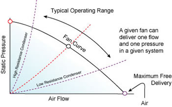 |
Figure
3. Illustration of fan law impacts on air flow
in AC condenser
|
- The
system static pressure (negative pressure on the underside
of the fan and over-pressure above the fan) increases
at the square of the air flow increase.
- As
static pressure decreases, the air flow increases along
the fan curve for a given fan.
- Fan
curves can have peak efficiency and stall regions with
implications for air moving performance and sound.
- With
a given fan and system pressure, the air mass flow rate
increases linearly with fan RPM.
- PSC
motors offer limited RPM selection: 825-850 rpm for 8
pole motors, 1,075-1,100 rpm for 6 pole motors and 1,450-1,500
rpm for 4-pole motors. Slower motors are preferred due
to sound implications.
- Brush-less
direct current (BDC) permanent magnet motors offer variable
speed control to select the RPM range over the range
to which it is programmed. Thus, these motors allow flexible
choice of condenser fan air flow without sacrificing
efficiency.
One
challenge within the research was to adequately measure
the external static pressure of the fan as operating within
the condenser. As shown in Figure 3, establishing this
value was critical to the fan and the achievement of good
performance. Within our testing, this was measured under
the fan, taking a traverse of the condenser cavity using
a precision digital manometer. Measurement of the pressure
above the fan and under the grill proved more difficult,
but sufficient data was obtained to facilitate a fan design.
The total external static pressure of the original fan
producing ~2200 cfm (1,038 L/s) was about 30 Pa (0.12 IWC).
Impact
of Air Flow on Outdoor Unit Condenser
As
expected, greater air flows across the condenser coil heat
rejection surfaces lead to greater cooling capacity and
slightly lower compressor power. A simulation was run implementing
the DOE/Oak Ridge Heat Pump model to examine the relationship
between motor power and airflow for a conventional 3-ton
cooling system (Fischer and Rice, 1985). This simulation
model has been well validated (Levins et al., 1997 and
Rosenquist, 1997) and allows detailed examination of how
system cooling performance is enhanced by increased air
flow across the condensing surfaces and how this trades
off against increase to condenser fan motor power. Figure
4 shows the relationship evaluated for a conventional AC
system.
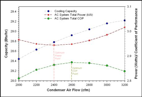
Figure 4. Evaluation of Optimum System Outdoor
Air Flow for a Hypothetical 3-ton air conditioner
Note
that the slope of the increased cooling system capacity
increases gradually with greater air flow, while the
required fan power increases rapidly with flow. As the
required shaft power will increase between the square
and the cube of the air flow, this exacts a real limit
on the air flow to be selected for a given condenser
design. Thus, the overall system electric power (including
compressor, and indoor and outdoor fans has an optimum
outdoor unit air flow where electric power is minimized
and another point where the system cooling coefficient
of performance (COP) is maximized. These two points are
close and between 2,400 and 2,600 cfm (1,133-1,227 L/s)
for the unit modeled. Not surprisingly, real AC units
of this size often have rated air flow of around 2,400
cfm (1,133 L/s).
It
should be noted, however, that the optimum condenser
coil face velocity and condenser air flow is affected
by the coil face area, coil depth and fin spacing (Green
and Roberts, 1996). Generally, the highest COPs are achieved
for coils with a large face area, operating at a high
evaporator temperature and a low air velocity (2 m/s).
However, as we had no control over the heat exchange
surfaces in the AC condenser in order to lower external
static pressure, the challenge for our research was to
design a fan and exhaust manifold for our test air conditioner
which would improve the overall air moving efficiency
and maintain or slightly increase flow.
Sound
Control
Although
improving condenser fan energy efficiency was the fundamental
goal of our research, a secondary objective was to reduce
sound levels due to the importance consumers place on
a quiet air conditioner. This is particularly important
with close lot lines where AC condensers can be near
to sleeping quarters in neighboring houses.
Sound
is measured in decibels (dB) above the background noise
level. As the scale is logarithmic, small changes can
mean large changes in sound level. For instance, 1 dB
is generally accepted as the minimum sound level difference
that people can discern. A change of 3 dB (20% change
in sound pressure) is noticeable and a 5 dB difference
is clearly noticeable. ARI Standard 270-1995 governs
the way in which sound levels are measured for outdoor
AC units.
The
importance of the sound issue is clearly illustrated
by a survey done of 550 individuals in Canada (Bradley,
1993) which found that complaints from air conditioner
noise dramatically increased when the sound level was
5 dB or more above background levels. Also, the same
survey found that homeowners expressed a willingness
to pay 12% more for a very quiet air conditioner.
Although
the topic of sound and vibration control within air
conditioning is quite complex, we describe here some
of the fundamental influences (Schaffer, 1991):
- Fan
rotation speed is a major factor in sound propagation
dB 1 = dB 2 + 50log 10 (rpm 1/rpm 2)
Thus, a fan moving at a 20% slower speed should exhibit
a 5 dB drop in sound level
- Other
factors:
- Vortex shedding: turbulent eddies in the wake of
the fan blade tips
- Turbulence due to the obstructions in the intake
or exhaust wake
- Fan motor vibration
- Harmonic resonance associated with the number of
blades
- Fan interaction with compressor noise
Within
our research, a key emphasis to reduce sound levels
was to operate fans more slowly with efforts made to
suppress fan tip vortex shedding and harmonic resonance
associated with fan blades.
Baseline Air Conditioning Unit
and Test Facility
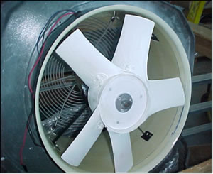
For our testing, we used a
standard 3-ton (10.6 kW) air conditioning
system produced by a major U.S. manufacturer.
The system uses R-22 refrigerant, although
our evaluation was done with condenser
fan only operation. The system has
a rated SEER of 12 Btu/Wh (SCOP = 3.51
W/Wh) when mated with a compatible
evaporator and air handler. The 19" (48
cm) fan in the original outdoor unit
consists of four metal paddle blades,
powered by a six-pole 1/8th hp (0.09
kW) PSC motor with a rated flow of
2400 cfm (1,133 L/s) for the condenser.
As measured in the baseline condition,
the fan motor drew 190-197 Watts at
208 Volts and produced 2,180-2,200
cfm (1,029 - 1,038 L/s) turning a 1,010
rpm. At the 95/80/67 ARI test condition
the fan power for the entire AC system
represents about 6% of total system
power.
For the research, we
needed to accurately
measure power, condenser
air flow, fan motor
power and rpm as well
as environmental conditions.
Secondly, we desired
to measure sound levels.
For diagnostic purposes,
we also used flow visualization
tools (smoke pencils
and flow wands) to
aid our understanding
of the air flow dynamics.
An indoor test facility
was constructed. A
precision power transducer
provided motor power
measurements ( +1 Watt
resolution) and air
temperature and relative
humidity. As the facility
had 208 single-phase
power, this electrical
source was used for
the measurements involved.
A laser tachometer
was used to measure
fan rpm and a precision
portable dB meter was
used to measure nearby
sound levels. A digital
manometer was used
to measure static pressure
within the condenser
underneath the exhaust
fan. As condenser air
flow was a critical
measurement, we constructed
flow measurement chamber
in conformance with
ASHRAE Standard 51-1985.
The constructed outlet
duct chamber with flow
straighteners and settling
screens was then calibrated
at another facility
with NIST traceable
air flow equipment.
The final chamber was
estimated to yield
an absolute air flow
measurement accuracy
of approximately +
5% (125 cfm or 59 L/s).
The relative air flow
measurement accuracy
was much better. We
found the equipment
could reliably measure
changes in air flow
as small as 20 cfm
(9 L/s) out of a 2,500
cfm (1,180 L/s) air
flow.
Development
of New Fans
In designing
fans, our objective was
to create the most efficient
designs while operating
at low rotational speed
to reduce fan noise.
We also looked to create
robust characteristics
which would provide good
performance over a range
of static pressure. This
is important as pressure
rise can change as condensers
foul or due to heat pump
outdoor unit frosting
during winter operation.
Generally, the true airfoils
we used have flatter
fan curves than those
for curved metal bladed
fans.
Over
a period of two years, a total of five different fans
were designed and built (designated A-E) with a series
of sub-variations on each. The differing fan configurations
were targeted for differing rpm ranges, static pressure
rise and sound characteristics. The Original Equipment
Manufacturer (OEM) design was a stamped 3-bladed metal
fan. Fans A and D consisted of three equally spaced
blades, with tapered and twisted air foild. Fan D was
designed for a higher pressure rise. Fan A5 was an
asymmetrical 5-bladed design. Fan E had forward curved
blades, intended to assist with sound reduction. Each
of the designs were evaluated by computer simulation
and then produced as three dimensional coordinate files
that could be used to describe the complex shapes.
Rapid prototyping was used to physically produce the
fan blades. Each fan was then hand-mounted onto a produced
hub and speed balanced before evaluation on the test
stand.
|
Figure 5. 19" Fan A5 with
asymmetrical blade spacing. |
The
fan design with an asymmetrical alignment has unequally
spaced blades. This configuration was explored to potentially
lower noise levels. This technology has been previously
developed for helicopter rotors (Kernstock, 1999),
but not previously utilized for AC condenser fans.
The sound of air rushing through an evenly spaced fan
rotor creates a resonance frequency with the compressor’s
hum, leading to a loud drone. But if the blades are
not equally spaced, this resonance is reduced producing
lower ambient sound levels. With our invention, we
took advantage of the asymmetrical characteristics
using a five-bladed fan design where the
fan blades are centered unevenly around the rotating
motor hub (Figure 5).
We tested each fan design with 1/8 hp (0.09 kW) PSC motors
either with six poles rotating at approximately 1075
rpm or eight poles rotating at 850 rpm. Over one hundred
tests were conducted over an 18 month period.
Advanced
Diffuser Design
Diffusers
are an expanding duct which provides recovery of air
static pressure by reduction of the flow velocity as
the flowing air mass expands. Practically, the condenser
fan air velocity is lowered prior to exhaust, thereby
increasing the overall mass flow rate from the system.
The exhaust configuration of a standard unitary air
conditioner consists of a short 4" (10 cm), 10
degree divergent diffuser covered by a slotted grate
or wire grill with the fan is nestled in the bottom
of the diffuser section.
Examining interactions between high efficiency propeller
designs and external static pressure, we determined
that an optimized diffuser section would allow large
improvements in air moving efficiency. Diffuser theory
would suggest that large improvements in fan efficiency
are possible by lengthening the diffuser stage (Blevins,
1984). Theoretically, an 18"(46 cm) diffuser
should provide about 25% added pressure recovery
over that from a short 4" (10 cm) diffuser (Japiske
and Baines, 1993). While a longer length would provide
still greater pressure recovery, we judged an 18" (46
cm) height to be the maximum practical for consumer
acceptance.
Thus, we constructed a larger 18" (46 cm) tall
7o divergent diffuser with the motor and fan located
in the bottom of the assembly. Figure 6 shows the
overall assembly as produced with the elongated diffuser.
Essentially this modifies the overall fan design
from more of a shallow ducted propeller to a true
tube-axial design.
|
Figure
6. Diagram of the improved condenser fan
with enhanced diffuser. |
The
diffuser increases the exhaust diameter from 19.75" (50
cm) to 24" (61 cm) at the wire grill top. While
testing with an experimental stator stage did not
demonstrate any added flow, we did find other changes
in geometry to yield modest improvement. As the motor
occupies the center of the diffuser, the swirl set
up by the fan as it expands through the diffuser
tends to collapse on the low pressure zone immediately
behind the motor. Through trial and error, we found
that by using a smooth conical center body on the
other side of the motor, we could increase flow by
20 cfm (9 L/s) and reduce power by about 2-5 Watts.
Reducing Tip Clearances and
Sound Control
The functionality of an
air conditioner condenser exhaust
is essentially analogous to a ducted
fan. Research done over the last
twenty years within aeronautical
engineering has shown that tip clearance
of ducted fan blades to diffuser
walls is critical to performance
(Rajagopalan and Zhang, 1989; Abrego
and Bulaga, 2002).
Unfortunately, low tip clearances are practically
difficult in manufacture due to required tolerances.
Should fan blades strike a solid diffuser wall,
the fan blades or motor may be damaged or unacceptable
noise created. Thus, in air conditioner fan manufacturing,
the fan blades typically have a gap of 0.3 to 0.4
inches (0.8 - 1.0 cm) to the steel sidewall diffuser.
This large tip clearance has a disadvantageous
impact on the ducted fan’s performance.
Considering the desirability of low sound levels
for AC condensers we examined interesting work
done at NASA Langley Research Center showing how
porous tipped fan blades in jet turbofan engines
can provide sound control by reducing vortex shedding – a
known factor in the propagation of excessive fan
noise (Khorrami et al. 2002).
Based on the research, we postulated that rather
than porous fan tip, a porous diffuser sidewall
could achieve the same result. This was done by
obtaining commercially available 3/16" (0.5
cm) open cell plastic foam 1 ½" (3.8
cm) wide, and applying it to the inner wall of
the diffuser assembly swept by the fan blades.
In actual application a UV stabilized open cell
neoprene foam would likely be used. As shown in
Figure 6, the foam is applied within the diffuser
assembly over the swept blade region to breakup
fan blade tip vortices and reduce sound. We also
used a solid tip clearance strip to test the differences.
Whereas the solid strip actually increased fan
noise, the open cell foam strip reduced noise markedly
(see Table 1).
One added advantage was that the foam can be used
to produce very close tip clearances in ducted
fans with no danger to the moving blades. Any contact
with the foam inner liner will be quickly worn
away to yield ideal fan tip clearances. This was
verified in overnight tests where tolerances were
exceeded. A final advantage is simplicity and cost
effectiveness. This is a simple change that can
potentially produce large improvements in acoustic
and air moving performance.
We estimated the flow and sound impacts of the
invention by carefully measuring performance of
two fans. Sound levels from fan only operation
were measured using hand-held dB meters at the
prescribed distance used for ARI 270-1995 for
the horizontal measurements. The results in the
Table 1 show a large improvement in airflow as
well as sound advantages.
Table
1
Impact on Performance of Reduced Tip Clearance
Using Foam Sound Control Strips |
|
|
Case |
Flow |
Power |
Normalized
CFM/W |
dBA |
OEM
Fan with slotted grill (1000 rpm) with
standard diffuser and top
|
Original
Configuration |
2200
cfm |
190
W |
11.6 |
63.0 |
A5
Fan with 8_pole motor (850 rpm) with extended
conical diffuser |
As
is (~1/4" clearance)
Tip clearance <1/32" foam |
2110
cfm
2300 cfm |
135
W
141 W |
15.6
16.3 |
62.0
60.0 |
A
Fan with 6 pole motor (1100 rpm) with conical
diffuser
|
As
is (~1/4" clearance)
Tip clearance <1/32" foam |
2400
cfm
2610 cfm |
139
W
145 W |
17.3
18.0 |
64.5
61.0 |
Note
the improvements in air moving efficiency. As the
shaft power requirement increases between the square
and the cube of the flow quantity, the advantage
of the foam strip for A5 (2,110 to 2,300 cfm) represents
a measured improvement in the air moving efficiency
of nearly 23%. Moreover, at three feet (1m) away
from the condenser, we measured sound reductions
of at least approximately two decibels (15% more
quiet to the human ear). In contrast, we had previously
attempted a number of other suggested improvements
(forward swept blades, dimpled air foils and winglets)
which did not produce any measurable sound reduction.
Tests Results
The fans were evaluated
with the standard slotted grill top
and later with the improved diffuser
configuration (elongated diffuser
with foam tip clearance strip and
conical center body). We also tested
with differing PSC motors (six vs.
eight pole operating at 1075 and
850 rpm, respectively). The process
involved measuring performance and
then evaluating the changes in a
comparative manner to isolate the
best options. The best performing
configurations with and without the
enhanced exhaust are summarized below.
Table 2 provides numeric data and
Figure 7 shows the graphical results.
Table
2
Comparative Performance of Fans & Diffuser
Elements |
| |
| |
Top |
Fan |
Motor |
Flow
(cfm) |
Power
(W) |
CFM/W |
Sound
(dBA) |
| * |
Slotted
Slotted
Slotted |
OEM
D
A5 |
6-pole
6-pole
8-pole |
2200
2190
1660 |
190
150
130 |
11.2
14.6
12.8 |
63.0
65.0
62.0 |
| ** |
Diffuser
Diffuser
Diffuser
Diffuser
Diffuser
Diffuser
Diffuser |
OEM
A5
A
A
E
E
D |
6-pole
8-pole
8-pole
6-pole
6-pole
8-pole
6-pole |
2250
2300
1930
2610
2500
1825
2590 |
173
141
111
145
132
109
150 |
13.0
16.3
17.4
18.0
18.9
16.7
17.3 |
63.0
59.0
58.0
66.0
65.0
61.0
66.0 |
| *** |
Wire-foam
Wire-foam |
OEM
A5 |
6-pole
8-pole |
2250
2110 |
188
146 |
12.0
14.5 |
62.0
60.0 |
*
Standard configuration, metal bladed fan |
**
Preferred configuration, with advanced fan
and diffuser with foam tip clearance strip |
***
Preferred configuration with standard top,
wire grill and foam control strip |
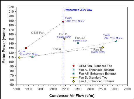
|
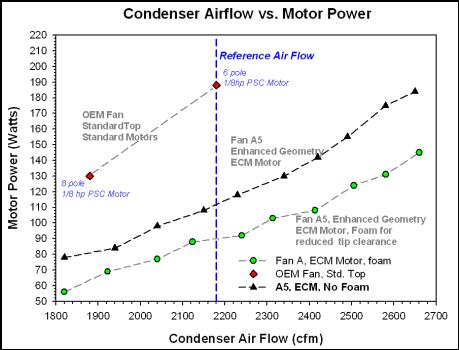
Figure
7. Performance of different fans with and without
the enhanced diffuser against the original
configuration |
Results
are shown for each fan, both with the slower 8-pole
motor (850 rpm) and the faster 6-pole motor (~1075
rpm). The best performing fan with the standard slotted
grill top and short diffuser was the three-bladed
Fan D which was designed for a higher pressure rise.
It produces the same flow as the standard OEM fan
(~2200 cfm or 1,038 L/s) with a power consumption
of 150 W vs. the 190 Watts for the standard fan at
208 Volts. Sound levels are similar to the standard
configuration.
We
also did a test of the original configuration
with a wire grill rather than slotted
top above the short diffuser. The
wire grill showed superior performance– likely
due to a lower pressure rise above
the fan. The power of the original
metal-bladed fan dropped by 2 Watts
with equivalent flow. When the foam
tip clearance strip was added to
the original short diffuser, flow
increased by 50 cfm (24 L/s) along
with a small drop in sound level.
Also shown are tests using the
enhanced diffuser with Fan A, Fan
A5 (a 5-bladed asymmetrical version
of Fan A) and Fan E. Two fans (B
and C) are not shown as results
were not promising.
Note
that the A5 fan with the diffuser improves air moving
efficiency (CFM/W or L/s/W) by greater than 46%. With
the enhanced diffuser, this was our preferred configuration.
It produced 100 cfm (47 L/s) more flow than the standard
configuration while still reducing power by 49 Watts.
Unlike Fan D, it also reduces sound since the enhanced
diffuser allows the use of a slower turning fan with
an 8-pole motor to achieve better flow. Fans A and
E allow superior flow over the original configuration
at even lower power, although sound levels are increased.
These results suggest that a fan such as A5 could be
run at even lower RPM using a variable speed motor
to provide greater power and sound reductions or conversely
run at higher RPM to provide greater flows.
Tests
with a Variable Speed Motor
To
examine how the new fan and diffuser designs would
compare with the standard design at a given flow, we
obtained a brushless direct current (BDC) 1/3 hp (0.25
kW) motor from a leading U.S. manufacturer. It was
programmed to be variable in speed from 0 - 1200 rpm
in response to a pulse width modulated DC signal. These
motors tend to be more efficient than PSC motors– by
approximately 15% at full speed, but with large differences
at lower speeds. Our tests verified these expectations
and also showed the full advantages of the air foil
fan designs as well as the enhanced diffuser when flow
was equivalent to the OEM design.
For instance, the OEM fan with the standard top and
1/8 hp (0.09 kW) PSC motor required 190 Watts to
provide 2,200 cfm (1,038 L/s) of flow at 208 Volts.
The original fan with the enhanced diffuser and the
BDC fan required 125 Watts to provide the same flow
(2200 cfm). Thus, the diffuser and the BDC motor
produced a power savings of 65 Watts or 34%. However,
Fan A5 with the enhanced diffuser, and BDC motor,
only required 86 Watts to provide the same flow – a
reduction in power of 102 Watts or 55%. The same
tests also showed that by increasing rpm with the
A5 fan up to 1,060 rpm, flow was increased to 2,410
cfm (1,137 L/s) with 106 W power draw.
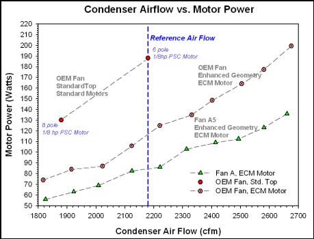
Within our research, we established that modulating
outdoor unit fans speeds may have attractive performance
and sound tradeoffs. We speculate that much of the
nuisance of air conditioner noise comes during nighttime
when ambient sound levels are low and occupants are
asleep. This suggests that the BDC condenser fan
speed might be modulated to high speed during very
hot daytime periods. For instance, fan speed could
be set to high above 94oF (34oC) while a low speed
would be used when the outdoor temperature wa less
than 84oF (29oC). This would substantially reduce
fan noise during evening hours while preserving best
peak performance during hot afternoons. Figure 8
below shows the comparative performance of the OEM
configuration, the OEM fan used with the enhanced
diffuser, and BDC motor with the improved fan design.
|
Figure
8. Impact of BDC motor and improved fan blades
on condenser performance. |
In
Figure 8, the impact of the diffuser and BDC motor
can be seen as well as the influence of the improved
fan blades. Finally, Figure 9 below isolates the airflow
improvement created by the tip clearance and sound
control foam strip when evaluated at differing flow
points with the BDC motor and the high performance
fan.
|
Figure
9. Impact on performance of Fan A5 used with
elongated diffuser with and without tip clearance
foam strip. |
Additional
Laboratory Measurements
In May 2004, we took
the prototype condenser top to a major U.S. air conditioning
manufacturer who possessed a sound room and air flow
measuring facilities to allow verification of measurements.
Within their laboratories, we found that measured
sound reductions of the new diffuser top were only
1-2 dB as measured according to the ARI 270-1995 standard.
This is likely due to the tendency of the longer
diffuser to broadcast sound upward to the overhead
microphones. We also were able to verify the flow
and power reductions previously measured. Power consumption
of the PSC motors, when tested at 230 volts was about
10 watts more than test done at 208 volts. However,
the savings with PSC motors at 230 volts could be
made similar to what we measured by slightly reducing
the shaft wattage of the motors for the improved
blades. This would reduce power waste as the motors
approach synchronous speed at higher voltage.
Conclusions
A research project designed,
fabricated and tested high efficiency
air conditioner condenser fans to
improve flow characteristics while
dropping motor power. We also examined
potential changes to the condenser
exhaust configuration to enhance
performance. The primary objective
was to reduce motor power while providing
similar or superior flow to the standard
configuration. A secondary objective
was to provide sound reductions which
is important to consumers.
Within the effort, we developed new twisted and
tapered propeller air foils that demonstrated greater
air moving efficiency. Fan only savings were 40
watts (21%) for the same motor and condenser top.
We
also showed how a lengthened diffuser with a conical
insert after the motor can improve air moving efficiency
by over 16% for standard fans and over 27% for high
performance fans. Fan tip losses and associated vortex
shedding was reduced though the use of a porous foam
strip to improve air flow performance while helping
to reduce sound. This also allows slower fans to
provide superior air moving performance along with
sound control. On the negative side, however such
design would lengthen condenser height by approximately
18" (46 cm) and somewhatincrease costs by increasing
sheet metal requirements.
The
fundamental project achievements are summarized below:
- Provides
49 Watt reduction in fan power (141 W vs. 190 Watts)
with PSC motors at 208 volts.
- Increases
condenser air flow by 100 cfm or 47 L/s (5% increase
in fan flow).
- Provides
102 W power reduction with BDC motor.
- Reduces
fan-only ambient sound level by 1-2 dBA. Ground level
sound reduction is greater.
- BDC
motor allows lower fan speeds for ultra-quiet night
operation, higher flows for maximum capacity during
very hot periods (temperature based control)
Key Technologies
- High
efficiency 5-bladed asymmetrical fan moves air
quietly at lower fan speeds.
- Diffuser
top for effective pressure recovery allowing increased
air flow at low speeds.
- Conical
center body reduces losses in exhaust swirl.
- Foam
sound control strip to reduce tip losses and fan
tip vortex shedding.
- Patents
pending: U.S. Application Serial No. 10/400,888,
Provisional applications 60/369,050 / 60/438,035 & UCF-449CIP; WhisperGuard (UCF-Doc
Acknowledgments
This work was funded by the U.S. Department
of Energy within its Building Technologies Division.
Thanks to Terry Logee for his support. Gary Nelson
and Ron Rothmann with The Energy Conservatory assisted
with development and calibration of the air flow
measurement equipment. At AeroVironment, Inc. John
Gongola and Guan Su assisted with creation of the
computer generated designs. In particular, we appreciate
the great skill of Shep Shepperd of Merritt Island,
FL in provided the precision machining to assemble
the prototypes and exhaust manifold configurations.
References
A. I. Abrego and R. W.
Bulaga, “Performance Study
of a Ducted Fan System,” NASA
Ames Research Center, American Helicopter
Society Aerodynamics, Acoustics and
Test Evaluation Technical Specialists
Meeting,” San Francisco, CA,
January 23_25, 2002.
ANSI/ASHRAE 51-1985 (Revision: ANSI/ASHRAE 51/AMCA
210_1999): Laboratory Methods of Testing Fans for
Rating, American Society of Heating, Refrigerating
and Air Conditioning Engineers, Atlanta, GA.
ARI, 1995. ARI 270-1995: Sound Rating of Outdoor
Unitary Air Conditioning Equipment, Air Conditioning
and Refrigeration Institute, Arlington, VA.
ASHRAE, 2004, “Chapter 18: Fans,” HVAC
Systems and Equipment, American Society of Heating,
Refrigerating and Air Conditioning Engineers, Atlanta,
GA.
R. D. Blevins, Applied Fluid Dynamics Handbook, “Nozzles,
Venturis and Diffusers,” Van Nostrand Reinhold,
NY, 1984.
J. S. Bradley, 1993, “Noise from Air Conditioners,” Institute
for Research in Construction, National Research
Council of Canada, Ottawa, ONT.
DOE/EIA, 1999. A Look at Residential Energy Consumption
in 1997, Energy InformationAdministration, DOE/EIA-0632
(97), Washington, DC.
S. K. Fischer and C. K. Rice, 1983. The Oak Ridge
Heat Pump Models: I. A Steady_State Computer Design
Model for Air_to_Air Heat Pumps, ORNL/CON_80/R1,
Oak Ridge National Laboratories, August, 1983
R. H. Green and L. Roberts, 1996. “The Effect
of Air-Coil Design on the Performance of Heat Pumps
and Air Conditioners,” ASHRAE Transactions,
Vol. 102, Part 1, pp.257_265.
D. Japikse and N.C. Blaines, 1993. Diffuser Design
Technology, Concepts ETI, Inc., White River, VT.
M. R. Khorrami, F. Li and M. Choudhari, 2001. “A
Novel Approach for Reducing Rotor Tip Clearance
Induced Noise in Turbofan Engines” NASA Langley
Research Center, American Institute of Aeronautics
and Astronautics, 7th AIAA/CEAS Aeroacoustics Conference,
Maastrictht, Netherlands, 28_30 May, 2001.
Nicholas C. Kernstock, “Slashing through
the Noise Barrier,” Aviation Today, August
1999.
W. P. Levins, C.K. Rice, and V. D. Baxter, 1997. "Modeled
and Measured Effects of Compressor Downsizing in
an Existing Air Conditioner/Heat Pump in the Cooling
Mode," ASHRAE Transactions, Vol. 192, Part
2, pp.22_33.
J. Proctor, Z. Katsnelson, G. Peterson and A. Edminster,
Investigation of Peak Electric Load Impacts of
High SEER Residential HVAC Units, Pacific Gas and
Electric Company, San Francisco, CA., September,
1994.
R. G. Rajagopalan and Z. Zhang, "Performance
and Flow Field of a Ducted Propeller," American
Institute of Aeronautics and Astronautics, 25th
Joint Propulsion Conference, AIAA_89_2673, July
1989.
G. J. Rosenquist, 1997. "Comparison of Simulated
and Measured Test Data on Air_Source Heat Pumps",
3rd International Conference on Heat Pumps in Cold
Climates, Wolfville, Nova Scotia, Canada, Aug.
11_12, 1997; Caneta Research, Inc., Mississauga,
Ontario, Canada, November, pp.391_405.
M.
Schaffer, 1991. A Practical Guide to Noise and Vibration
Control for HVAC Systems, ASHRAE, Atlanta, GA.
Click
here for PDF Version
|


