|
II.
BAIHP Technical Assistance (F)
- Fleetwood
Homes
Category D, 500 Homes Auburndale, Florida
factory
FEMA Homes
In September of 2004 BAIHP researchers tested and inspect
single-wide homes built by Fleetwood under contract with
the Federal Emergency Management Agency (FEMA) to identify
possible areas of moisture-related damage and provide
recommendations to mitigate problems.
These homes are destined for victims of hurricane Charley
in Southwest Florida. Various singlewide floor plans
are being constructed with the typical size being 14x66,
several of which were tested for duct and envelope tightness.
Other construction specifics include:
- In-line, metal floor
duct system with 1 or 2 short branch ducts
- Duct risers
sealed with mastic
- Branch duct joints sealed with mastic,
then covered with metal tape
- Down flow gas furnace
installed in central hallway
- Large door undercuts
plus small door-mounted return vent in bedrooms
- Central
exhaust fan ventilation strategy
- Vinyl interior wallboard
throughout
- Vinyl exterior siding
FEMA-required specifications that differ from typical
Fleetwood design include:
- Vinyl flooring throughout
- Double
floor decking (½-inch OSB over ½-inch
plywood)
- R22 floor insulation
- “Chicken wire” installed
below the belly board
- 80% AFUE, 70 kBtu gas furnace with
no cooling installed
- FEMA
provides a 2.5-ton split system (coil & condenser)
to be installed on-site
- Goodman
CKL30-1L condenser & Mortex
96-842J-OP A-coi
Cooling System and Air Handler Issues
The immediate concern with these homes is the FEMA-provided
cooling system that, at 2.5 tons, may be oversized for
the application. This, coupled with the fact that a vapor
barrier is located on the wrong side of the exterior
wall and floor assemblies, increases the potential for
moisture damage to those surfaces. Other issues that
can impact the moisture durability of these homes are
addressed below, but initial envelope and duct test results
indicate no immediate cause for concern.
A properly sized cooling system should be an integral
part of any strategy to mitigate moisture damage in a
hot humid climate. We recommend using the latest version
of Manual J calculations to determine proper cooling
system size and it appears these homes may be oversized
by as much as one ton. Oversized systems are prone to
short-cycling for much of the year which tends to cause
higher indoor humidity levels than properly-sized systems.
Another issue with an oversized system is it allows
homeowners to maintain lower indoor temperatures than
might otherwise be possible. Maintaining indoor temperatures
below the outdoor dewpoint can lead to moisture damage
over time especially in homes with interior vapor barriers
(vinyl floor and wallboard). Average summer ambient dew
point temperatures in Southwest Florida are in the low
to mid-seventies.
Beyond reducing the cooling system size, some benefit
can be gained from adjusting the air handler fan speed
in cooling mode and adding outdoor air ventilation. Lower
airflow over the coil will remove more moisture, help
to reduce indoor RH levels and possibly encourage higher
thermostat settings by the occupant. Adding a passive
supply (not more than 40CFM) of outside air to the return
side of the air handler will promote positive pressurization
of the home which may lessen the likelihood of moisture
damage to wall and floor assemblies.
In-Plant Construction
Metal duct fabrication was observed during production
where mechanical fastening and sealing methods appeared
suitable for a tight durable system. Duct ends and branch
duct joints were first fastened with screws then mastic
was applied by tube. Metal tape was placed over the mastic
(shown below at top right). This method produced tight
duct systems as demonstrated by the 3 to 4% leakage rate
found in four completed homes.
The continued use of mastic is encouraged for a long-lasting,
positive seal. While there is little harm in using metal
tape over mastic it does not provide much additional
sealing. One possible drawback of tape over mastic is
that it may hide gaps that could otherwise be seen and
corrected by workers. Applying mastic alone by brush
should prove adequate and less costly. A fabglass mesh
is useful when applying mastic by brush to cover any
large gaps that may occur.
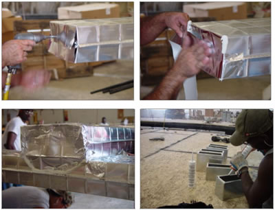
Figure 16 Metal duct fabrication
on FEMA homes,
Fleetwood plant – Douglas, GA
A bead of mastic was applied to supply risers (Figure
16 bottom right photo) prior to being attached to
the trunk line with screws. Once the riser was attached
an opening in the trunk line was cut out. The same method
was used for the return plenum riser. This method can provide
a positive seal when adequate mastic is applied – not
always certain from observations on the production floor.
Although testing showed four such systems to be fairly
tight, some leakage at the risers was evident at the interface
of the thin metal of the trunk and riser collar where unfilled
gaps where found.
To prevent leakage at risers, mastic should be visibly squeezed
out at the interface when attached. The mastic bead should
be 1/2 to 5/8 inch in diameter (size of your little-finger)
to allow full contact between surfaces.
Post-Production Testing
Four newly completed singlewides (all 14x66) were tested
at the Douglas plant. Total duct leakage was measured on
all homes but only two homes were measured for envelope tightness
and duct leakage to out.
Table
12 Envelope and Duct Tightness Test Results
Four
14x66 FEMA Homes (Area = 924 ft 2)
|
Unit |
CFM50 |
ACH50 |
cfm25tot |
cfm25out |
Qn |
14x66 |
646 |
5.6 |
32 |
20 |
0.022 |
14x66 |
709 |
6.1 |
42 |
26 |
0.028 |
14x66 |
. |
. |
46 |
. |
. |
14x66 |
. |
. |
49 |
. |
. |
Notes:
Only 2 homes tested for envelope airtightness & duct
leakage to out |
Blower
door testing showed the envelope on the tighter side (0.73
CFM50/ ft 2) of the airtightness range typically found in
new homes (0.75 to 1.0 CFM50/ ft 2). Of greater importance
is where this leakage occurs. With sheet vinyl flooring installed
throughout these homes, air leakage through the floor is
the biggest concern. A history of floor moisture damage has
been documented in manufacture homes located in hot/humid
climates where vinyl products are installed. Increased air
leakage between the floor and belly has greater potential
to force outside air into the belly should a negative pressure
situation arise in the home (caused by duct leakage and/or
inadequate return air transfer). Both the interior floor
surface and the exterior belly board should be sealed as
tightly as practicable. Plumbing penetrations make up most
of the holes through upper floor surface and can be difficult
to seal. One simple option currently being used by the
Fleetwood plant in Washington state involves the use of a
EPDM rubber sheet cut to fit plumbing pipes and stapled in
place prior to vinyl flooring installation, providing a durable,
flexible seal (Figure 17).
|
Figure
17 Rubber
seal –
Washington
Fleetwood plant. |
One 14x66 home was tested for interior pressure imbalances
by turning on the air handler fan. Depressurization of the
interior space can occur if duct leakage is excessive or
insufficient return air pathways exist between rooms with
closed door. No detectable depressurization was measured
during the test indicating sufficiently tight ducts and adequate
return air pathways from closed rooms.
Duct system airtightness testing showed four systems in
14x66 singlewide homes to have duct leakage rates to out
of between 2 and 4% of conditioned floor area at 25 Pascals.
A value of 3% is generally considered sufficient to inhibit
negative pressurization of the conditioned space. Leakage
to out was directly measured in the first two test homes
at 2 and 3%, while the last two homes were judged to be slightly
higher as inferred by the measured total leakage rate. While
these leakage numbers are good, only a small amount of leakage
is necessary to dramatically increase the leakage percentage
in homes of such relatively small size.
There are three general areas in these duct systems where
leakage is likely to occur:
- End of duct runs
- Trunk to branch connection
- Supply risers and the air handler supply plenum
The first two of these areas were isolated and tested by
duct blaster in the plant on a newly fabricated system prior
to installation in the home. This particular duct system
had only one branch connection whereas the four previously
tested homes had two branches. Results showed a leakage rate
of about 8-10 CFM at 25 Pascals, attributed to two closed
duct ends and one branch to trunk connection. This would
indicate that on the four duct systems tested earlier (with
two branches each), roughly one-half to two-thirds of the
leakage to out (20 to 30 CFM50) occurs at duct ends and branch
connections with the remainder occurring at the risers and
plenum.
Fleetwood Factory Visits in 2002-05
In 2002, researchers visited four Fleetwood factories in
southern Georgia to investigate the cause of moisture-related
building failures when units were installed in a hot-humid
climate. The factories are located in Douglas, Alma, Pearson,
and Willacootche. As a result of FSEC recommendations, the
factories have changed their duct construction practices
and are now constructing airtight ducts with mastic.
Six
Fleetwood homes, all in Florida, were tested for moisture
and mold damage from April 2002 through March 2003. All
of the homes had damaged flooring due in part to a lack
of ground cover and poor crawlspace ventilation. Damage
to the floor in one home was exacerbated by a plumbing
leak. Only one home had moisture damage to the wallboard
material, and this home showed a history of thermostat
settings below 72° F.
A report for each home was submitted to Fleetwood for corrective
measures. One additional high bill complaint in Cobb, Georgia
was investigated during that period. Between April 2003 and
October 2004 ten Fleetwood moisture damaged homes were investigated
by BAIHP, seven in Florida, one in Texas, and two in Georgia.
In May 2003, FSEC researchers were asked by Fleetwood and
Coleman to travel to Fleetwood's five southeastern plants
and test three homes built by each factory to get their plants
certified for building EnergyStar Homes. A sample of the
data collected is shown in Table 13.
At the Auburndale, FL plant, BAIHP researchers conducted
the tests in houses set up in the factory's parking lot.
The houses did not have air handlers, but total duct leakage
was within range to achieve Fleetwood's goal for this plant
which was to build houses according to the EPA EnergyStar
Building Option Packages (BOPs) for manufactured housing,
Climate Zone 4, and to attain a less than 5% duct leakage
rate (Qn,total #5%). The houses showed some need for additional
envelope sealing which was implemented after the first house
was tested. The other two houses showed marked improvement
in whole house air tightness. Recommendations and test results
were provided to Fleetwood via email (no formal trip report).
Similar testing was conducted at the Georgia Fleetwood factories
in Willacoochee, Pearson, Douglas, and Alma.
Table
13 Test Results, Factory Certification at Fleetwood’s
Auburndale facility |
House
# |
Size |
ACH50 |
Estimated
natural ach (ACH50/18) |
Qn
total
(CFM25 total/cond. area)
|
1 |
24 X 48 |
8.7 |
0.48 |
0.031 |
2 |
28 X 52 |
5.5 |
0.31 |
0.034 |
3 |
28 X 52 |
5.5 |
0.31 |
0.029 |
Woodland, Washington
Category C, 222 homes
Industry partner Greenstone has been working with BAIHP staff and SGC/E-STAR
manufacturers to evaluate a hybrid floor insulation system. These systems,
composed of one R-11 belly blanket and R-22 blown cellulose insulation eliminates
over-compression and reduces the chance of leakage during transport and set-up,
while minimizing material and labor costs. Fleetwood Homes of Washington
adopted this system for all of their homes in 2001. Other manufacturers have
adopted the hybrid floor insulations system, which provides less insulation
voids and reduces first cost of R33 floor system over 3-R11 fiberglass batts.
One potential consequence of using the hybrid system is increased moisture
in the belly; in 2003, BAIHP staff installed data loggers in two homes to
determine whether this is a problem; after the data loggers were retrieved
in 2004, BAIHP staff submitted a report to Fleetwood suggesting no dew point
problems within the floor system (Figure 18).
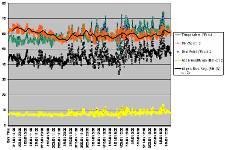
Figure 18 Temperature and Dew Point Under Hybrid Floor
Decking
- Florida
International University, 2005 Solar Decathlon
Miami, FL
FSEC provided technical assistance to FIU (Florida International
U.) for the 2005 Solar Decathlon (http://www.eere.energy.gov/solar_decathlon/).
An introductory meeting was held at FSEC in October 2003.
Subsequently, a design competition was held among FIU
students and the team, comprised of architecture and
engineering students, to merge the 10 winning designs
into a single conceptual design. In April, the team met
with BAIHP researchers at FIU to review the schematic
drawings and model.
Researchers
discussed strengths, weaknesses and technical needs of
the schematic design including cooling loads and strategies
for mitigating each (reflective roofing, advanced glazing,
shading, ventilation, point source moisture exhaust, etc.),
building integrated solar (PV) systems, solar water heating,
mechanical system design, energy storage, construction
challenges, and the aesthetics of energy efficiency. Students
plan to use ray tracing capability of the CAD tools they
are already using to study shading and daylighting and
will schedule another review with BAIHP researchers this
summer as they move into design development.
|


 You
are here: >
You
are here: > 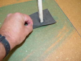