


Testing and Monitoring of the READ Project House
East Lansing, Michigan*
Prepared for:
United States Department of Energy
Office of Building Technology
State and Community Programs
1000 Independence Ave. SW
Washington, DC 20585
George James, Program Manager
Prepared by:
Armin F. Rudd
Florida Solar Energy Center
1679 Clearlake Road
Cocoa, FL 32922
11 February 1999
EXECUTIVE SUMMARY
The Resource Efficient and Affordable Demonstration (READ) project in East Lansing, Michigan is an 1800 ft2 entry level house. The house design originated from the Center for Housing Innovation at the University of Oregon and was modified by John Barrie Associates. The most significant changes to the original design was the addition of a full basement in place of a crawl space, and an enlarged front porch. The entire building envelope, including basement walls, was constructed with structural insulated panels (SIPs). Several private companies collaborated on the project. The U.S. Dept. of Energy, Energy Efficient Industrialized Housing (EEIH) program supported the energy and environmental testing and monitoring through the Florida Solar Energy Center (FSEC).
Measurement of formaldehyde concentration (41 ppb) taken in the READ project house fell well below the most restrictive reference level (50 ppb). Total volatile organic compounds (TVOC) concentration (11 mg/m3) was high compared to a commonly used reference guideline for TVOC concentration (1 mg/m3) and other houses tested by FSEC. This may have been due to the hardwood floor finish, or the large amount of engineered wood (OSB) used in the structure.
With 15oF outside temperature and 68oF inside temperature, infrared scanning revealed no thermal insulation or air barrier defects that would have a significant impact on energy use or comfort.
This house had very little building envelope air leakage relative to much of conventional construction. In fact, at 1.7 air changes at 50 Pa pressure difference, it was one most airtight houses tested by the EEIH program to date. Duct leakage to outside was essentially zero, as would be expected since the ducts were completely within the conditioned space.
Energy consumption was low for the 1800 ft2 house. Heating energy consumption was less than $30 per month over the 31 month monitoring period (3 heating seasons). Total gas and electric energy consumption was less than $75 per month. Average indoor temperatures were usually within 3oF between the first and second floors, and those floors were within 8oF of the basement. Indoor relative humidity was good, between 35% and 60%. However, carbon dioxide levels were elevated indicating a lack of enough fresh air for reduction of indoor odors created by people. It is recommended that the ventilation fan operation time be increased.
INTRODUCTION
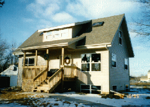
The Resource Efficient and Affordable Demonstration (READ) project in East Lansing, Michigan is an 1800 ft2 entry level house constructed with the goal ".to strengthen the understanding of highly energy-efficient building technology and demonstrate its applicability and economic availability to the community-at-large."
The project planners set out to build the entry level house designed by the Center for Housing Innovation at the University of Oregon, called the Stressed Skin Insulated Core (SSIC) Demonstration House. The only major change to the original SSIC demonstration house plan was that the READ project house would have a full basement instead of a crawl space. The basement walls were also of Structural Insulated Panel (SIP) construction, with pressure treated plywood outside skins. Other changes included: altering the proportions of the original design, making the front porch deeper and wider, lowering the profile of the house relative to the site, adding a feature window in the living room, and some economic-based changes. The house was targeted in the $70k to $90k range depending on interior finish choices.

The project team consisted of participation, and some cost sharing, from several private sector groups, including:
- John Barrie Associates, Architects- an environmental design architecture firm
- Great Lakes Insulspan- producers and designers of structural insulated panel systems
- Sunway Builders- builders for the READ project
- Consumers Power Company- local gas and electric utility
- Urban Options- a non-profit organization that serves as an advocate for energy efficiency
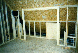
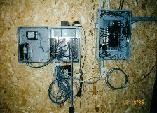
Through its Energy Efficient Industrialized Housing (EEIH) program, the United States Department of Energy supported the READ project with energy and indoor air quality testing and monitoring to evaluate actual performance. In September of 1995, during construction, the Florida Solar Energy Center (FSEC) pre-wired the house for monitoring sensors. In December of 1995, building diagnostic testing was completed, and the energy and environmental monitoring system was made operational. At that time, two local television stations featured the testing project on their news programs. By telephone modem, energy consumption and indoor/outdoor environmental data was collected between December 1995 and June 1998.
Heating, Ventilating, and Air Conditioning Systems
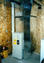
The heating, ventilating, and air conditioning (HVAC) systems installed in the READ project house were as follows:
- Heating- 90+ efficiency, direct vent (sealed combustion) natural gas furnace
- Cooling- conventional direct expansion refrigeration cooling system
- Ventilation- in-line fan with programmable controller (Airetrack) for ventilation (The in-line fan drew outdoor air and supplied it to the plenum of the furnace. If the furnace fan was not on, the air could move back through the fully-ducted return system to each room.)
Domestic Hot Water and Other Appliances
The domestic hot water heating system and other appliances in the READ project house were as follows:
90+ efficient natural gas, direct vent (sealed combustion) domestic hot water heater
- natural gas range and oven
- electric dryer
TESTING RESULTS
Indoor Air Quality Sampling
Indoor and outdoor samples were taken to measure the concentration and emission rate of volatile organic compounds (VOCs) and formaldehyde. During indoor sampling, the house air infiltration rate was also measured by the tracer gas decay method. This allowed calculation of the emission rate from indoor sources. Diaphragm pumps and mass flow controllers were used to sample a precise volume of air for analysis. Paired VOC samples were collected over a 40 minute period using multi-sorbent samplers. Single formaldehyde samples were collected over a 1 hour period using a DNPH-Silica Sep Pak cartridge. Laboratory analysis of the samples was conducted by Lawrence Berkeley National Laboratory using a gas chromatograph-mass spectrometer system.
The VOC and formaldehyde analysis results are presented in Table 1, along with comparison to samples taken by FSEC from other residential test sites.
Table 1 VOC and formaldehyde analysis results
| READ
project
MI |
PA-1
min/ |
PA-2
min/ |
FL-1 |
FL-2 |
FL-3
min/ |
FL-4
min/ |
FL-5
min/ |
FL-6
min/ |
TX |
|
| TVOC concentration (mg/m3) | 10.8 | 2.39 | 2.84 | .65 | 11.8 | 1.5 | .954 | 2.96 | 1.73 | 1.58 |
| TVOC
emission rate
(mg/m2-h) |
2.69 | 1.24 | 2.34 | .363 | 8.41 | 1.89 | 1.41 | 2.41 | 1.51 | .946 |
| Formaldehyde
concentration
(ppb) |
40.9 | 28.4 | 39.9 | 30.8 | 53.8 | 20.9 | 36.0 | 40.4 | 39.7 | 13.9 |
| Formaldehyde
emission rate (mg/m2-h) |
12.2 | 20.7 | 42.1 | 21.6 | 43.8 | 28.8 | 68.0 | 38.1 | 41.7 | 10.3 |
The most restrictive formaldehyde concentration guideline set by a government agency is 50 ppb (CARB). The measurement taken in the READ project house falls well below that level. A commonly used reference guideline for TVOC concentration is 1 mg/m3. The measurement taken exceeds that by ten times. The TVOC concentration and emission rate was also on the high side compared to the other houses listed. This may have been due to the hardwood floor finish, or the large amount of engineered wood (OSB) used in the structure.
Thermal Insulation Quality Testing
Evaluation of thermal insulation quality and air leakage pathways was made using infrared imaging equipment. Infrared scanning helps to locate areas where insulation details could be improved and to locate areas of thermal insulation defect. Infrared imaging readily shows conduction through framing components, misplaced or missing insulation, and convective air paths which short circuit insulation. An Inframetrics model 600L color infrared radiometer system was used. Two thorough scans of the house thermal envelope were made from the interior side and one from the exterior. Images of interest were recorded on VHS tape.
The first interior and exterior scans were done with the house in a thermally undisturbed state, that is, the heating system had been on at the same setpoint for at least 24 hours and the house was being operated normally. This gave a baseline view of the house thermal envelope.
The second scan was done with the house depressurized to -25 Pa with respect to the outdoors. This procedure simulates elevated pressure influences such as wind, stack and exhaust devices. As outdoor air moves through any leaks in the thermal envelop, infrared scanning clearly shows the presence of air leakage paths and how they can affect the building's thermal envelop and ultimately it's energy consumption. After locating general areas of air leakage, the leaks can be pinpointed by reversing the blower door fan so that the house is pressurized to about 15 Pa above outdoors and using a chemical smoke pencil to show the location of exfiltrating air.
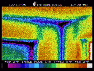
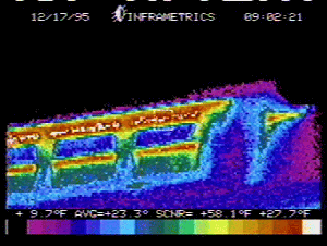
With 15oF outside temperature and 68oF inside temperature, the infrared scanning revealed no thermal insulation or air barrier defects that would have a significant impact on energy use or comfort. However, a few defects were observed as follows:
- headers over second story shed dormer window (front of house), likely uninsulated solid lumber header, see Figure 4;
- both sides of shed dormer, triangular section, see Figure 4;
- other, mostly conductive, thermal shorting at corners, wall to 1st floor ceiling connection, and some panel splines, see Figure 5.
Building Airtightness Testing
Building air leakage was measured using a calibrated fan (Ductblaster) to depressurize the house. The fan was installed in a blower door frame in the exterior door at the rear of the house. Three multi-point fan de-pressurization tests were performed on the house. For the first test the supply registers and return grilles were open, for the second test, they were taped off, and for the third test, the outside air inlet for the ventilation system was also taped off. Table 2 lists the results. The results show that this house had very little air leakage relative to much of conventional construction. In fact, it was one most airtight houses tested by the FSEC EEIH program to date.
Duct leakage to outside was essentially zero, as would be expected since the ducts were completely within the conditioned space. The vaulted ceiling SIP structure lends itself well to this advantage. Another good feature of the air distribution system was that each room had a separate return duct. Separate return ducts reduce or eliminate room pressurization that occurs if the return air path is restricted. If central return ducts are used, properly sized transfer grilles/ducts should be installed to connect closed rooms to the central area.
Table 2 Building airtightness testing results
| Test ID# |
1 |
2 |
3 |
| Test Description | Ducts open | Ducts closed | Ducts closed
Outside air inlet closed |
| cfm50 | 531 | 531 | 467 |
| cfm50 per ft2 floor | 0.30 | 0.30 | 0.26 |
| ach50 | 1.93 | 1.93 | 1.70 |
| ELA in2 @4 Pa | 28.7 | 29.1 | 23.7 |
| EqLA in2 @10 Pa | 54.3 | 54.7 | 45.9 |
| Flow coefficient C | 40.8 | 41.6 | 32.6 |
| Flow exponent n | 0.656 | 0.651 | 0.681 |
| correlation coef. R2 | 0.99826 | 0.99880 | 0.99984 |
| ach annual estimate | 0.12 | 0.12 | 0.10 |
| cfm annual estimate | 33.4 | 33.8 | 27.6 |
Building Air Change Rate by Tracer Gas Decay
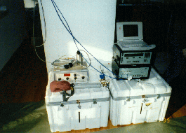
While the fan pressurization method of determining building air leakage allows the estimation of building air change rate with prescribed enviromental conditions, the actual building air change rate at any given time can be measured by tracer gas methods. The actual building air change rate was measured using: sulfur hexafluoride (SF6) as the tracer gas, a multi-zone photo acoustic gas analyzer, and a mass flow controller for constant injection of the tracer gas. Building air change rate varies over time due to influences of wind, thermal buoyancy, mechanically induced air flow, and door/window operation. Figure 8 is a plot of the hourly average air change rate as measured in four different locations in the house, including: the basement, 1st floor, and 2nd floor. Figure 9 is a plot of the hourly average air change rate with all four samples averaged together. The time period spans 14 hours of measurement from 10 pm to 9 am. During this time, the house was occupied and the ventilation system was operating. The average air change rate over the 14 hour period was 0.17 h-1.
ENERGY AND ENVIRONMENTAL MONITORING RESULTS
Table 3 lists the channels of monitored data taken between December 1995 and June 1998. The data was retrieved daily from the on-site datalogger over a dedicated telephone line. Measurements were taken every six seconds and averaged or totaled for storage every 15 minutes. The data was later processed into hourly and daily intervals for analysis and reporting. Summary data is presented here in the body of the report, and Appendix A holds numerous plots of supporting data for the three heating seasons covered by the monitoring period. The plots in Appendix A show an hourly averaged 24-hour profile that represent each month.
Table 3 Measurement channels for energy consumption and indoor/outdoor environment
| Channel # | Measurement description |
| 1 | Total electrical consumption (W-h) |
| 2 | Total gas consumption (ft3) |
| 3 | Ventilation fan electrical consumption (W-h) |
| 4 | Ventilation fan duty cycle (% on/off) |
| 5 | Ventilation fan status changes (on/off cycles) |
| 6 | Heating/furnace gas consumption (ft3) |
| 7 | Basement temperature (F) |
| 8 | 1st floor temperature (F) |
| 9 | 2nd floor temperature (F) |
| 10 | Outdoor temperature (F) |
| 11 | 1st floor relative humidity (%) |
| 12 | 2nd floor relative humidity (%) |
| 13 | Outdoor relative humidity (%) |
| 14 | 1st floor carbon dioxide concentration (ppm) |
| 15 | Horizontal solar radiation (W/m2) |
 Electric and gas energy consumption is shown as kilowatt hours
per day (kW-h/day) in Figure 11 for the entire 31 month monitoring
period. The kW-h/day value is the average of the daily sums for
each month. The gas energy consumption was converted from cubic
feet of gas by the approximate heating value of 1000 Btu/ft3
and the unit conversion of 3413 Btu per kW-h.
Taking into account the actual gas utility cost factors (electric=$0.0621/kW-h; gas=$0.0136/kW-h), Figure 12 shows a lot of the average daily energy cost in dollars per day ($/day) for each month.
Figure 13 shows the gas heating cost per month, and Figure 14 shows the total gas and total electric energy cost per month.
Energy consumption was low for the 1800 ft2 house. Heating energy consumption was less than $30 per month over the 31 month monitoring period (3 heating seasons). Total gas and electric energy consumption was less than $75 per month. Average indoor temperatures were usually within 3oF between the first and second floors, and those floors were within 8oF of the basement. Indoor relative humidity was good, between 35% and 60%. However, carbon dioxide levels were elevated indicating a lack of enough fresh air for reduction of indoor odors created by people. It is recommended that the ventilation fan operation time be increased.
REFERENCES
CARB. 1991. Indoor Air Quality Guideline No. 1: Formaldehyde in the Home. Californina Air Resources Board, Research Division, Sacramento, CA.
ACKNOWLEDGEMENT
This work was supported by the United States Department of Energy, Assistant Secretary for Energy Efficiency and Renewable Energy, Office of Building Technology, State and Community Programs, Energy Efficient Industrialized Housing program, George James-Program Manager.
APPENDIX A-1
1995-1996 Heating Season
Energy Consumption and Indoor/Outdoor Environmental Conditions
Monitoring
APPENDIX A-2
1996-1997 Heating Season
Energy Consumption and Indoor/Outdoor Environmental Conditions
Monitoring
APPENDIX A-3
1997-1998 Heating Season
Energy Consumption and Indoor/Outdoor Environmental Conditions
Monitoring
APPENDIX B
Infrared images of the READ project house
with 15oF outside temperature and 68oF
inside temperature
United States Department of Energy
Office of Building Technology
State and Community Programs
1000 Independence Ave. SW
Washington, DC 20585
George James, Program Manager
BAIHP Home | Overview | Case Studies | Current Data
Partners | Presentations | Publications | Researchers | Contact Us
Copyright © 2002 Florida Solar Energy Center. All Rights Reserved.
Please address questions and comments regarding this web page to BAIHP Master