|
Presented at the "1993 EEBA/NESEA Conference
on Building Solutions" conference, sponsored by the Energy
Efficient Building Association, Minneapolis, MN., in Boston, MA,
March 3-6, 1993.
Measured Air-Tightness and Thermal Insulation Quality of 11
Industrialized Houses
Armin Rudd
Subrato Chandra
John Tooley
Abstract
Building air-tightness and thermal
insulation quality has been evaluated for five major industrialized
housing manufacturers in the U.S. A small sample size of 11 houses
has been tested to date. The sample includes factory stud-frame panelized,
foam core panel, and modular construction. Reference air-tightness
numbers such as air change rate at 50 Pascal pressure difference,
effective leak area, equivalent leak area, and specific leak area
are reported. For the houses with forced air distribution systems,
a duct leakage and house pressure balance analysis was also conducted.
Special attention was paid to the air distribution system and its
impact on energy efficiency, health, safety and durability. Thermal
insulation quality was evaluated using an infrared imaging system.
Infrared images showing conduction through framing components, misplaced
or missing insulation, convective air paths which short circuit insulation,
air leakage in marriage walls and duct leakage are presented.
Introduction
The Energy Efficient Industrialized
Housing (EEIH) project, sponsored by the U.S. Dept. of Energy, seeks
to help industry increase the energy efficiency of its products and
increase its productivity. One of the ways industry can take advantage
of the EEIH project by participating in a short but intensive two-and-a-half-day
Process and Energy Efficiency Review (PEER) visit. It was in the context
of the PEER procedure that the results reported here were obtained.
Typically, between six and nine members of the EEIH project team visit
the industrialized housing manufacturer. On the morning of the first
day of the PEER visit there is an introductory briefing by the EEIH
team and the housing manufacturer, followed by a plant tour. By early
afternoon of the first day, the team's energy, manufacturing and design
groups split up and begin work in their specific task areas. The energy
group tests model homes for thermal insulation quality and building
air leakage, using an infrared scanning system and a blower door.
The manufacturing group evaluates areas such as labor productivity,
materials handling, inventory management and manufacturing methods.
The design group performs an assessment of design and marketing methods.
Day two is a continuation of work in the separate task areas. The
PEER visit concludes on the third day after a two-hour exit briefing
with the CEO and senior management. Recommendations are made and discussed
in each of the energy, manufacturing and design areas. A written report
follows.
On the average, houses are much more air tight than they were a decade
ago (Palmiter et al., 1991). Advances in materials which let moisture
pass through while providing great resistance to air flow have made
"air barriers" commonplace in building construction. Increased consumer
and builder awareness through education has contributed greatly to
reducing the energy lost by air leakage in houses. There are still
issues remaining, however, and some just recently coming to the forefront,
such as the effect of air distribution systems on energy use, occupant
health and safety, and material durability . A remaining issue is
that of air quality (Tsongas et al., 1992)--just how tight is too
tight to maintain good air quality throughout a house, and what is
the definition of good air quality? Can the meaning of good air quality
be effectively quantified? Typically, the driving force behind ventilation
in housing has been to either meet the prevailing ASHRAE recommendation
of 0.35 air changes per hour (ASHRAE, 1989), or to provide enough
ventilation to avoid obvious moisture problems in the house. Some
builders are afraid to take extra care to air tighten a house since
they may be forced to deal with ventilation issues which could increase
the cost of their product too much. Dealing with the problem from
a moisture control view point, others are reluctant to install vapor
retarders on ceilings, stating that they would rather let excess moisture
migrate through the entire ceiling area to the attic, where it may
not have a deleterious effect for a long time, rather then get a call-back
due to condensation on windows or moisture damage to drywall at poorly
insulated locations. These fears are understandable when so many houses
are constructed by small companies trying to make a modest profit
and often-times utilizing whatever labor help is available. Housing
manufacturers, however, through advanced process control, a more stable
and experienced work-force, and the economy of scale, should be able
to set aside these fears and produce energy efficient houses knowing
that the houses will function properly as complete systems.
A systems approach to constructing houses takes into account how
the different building components should work together instead of
working against each other. For instance, air leakage paths can completely
short circuit insulation, regardless of the R-value, rendering it
ineffective. The major system components in a house which affect energy
efficiency are: the weather resistant skin, the insulation (thermal)
envelop, the structural envelop, the interior finish skin, house wiring
and plumbing, ducts, air circulation fans, exhaust devices such as
bath and kitchen fans and dryers, combustion appliances, interior
doors, recessed light fixtures, and the list could go on. The systems
approach to house construction is difficult to achieve when so many
different trades and independent companies are involved as they are
in the site building process. Even when the building codes are strict,
code enforcement is the limiting factor; many people performing this
important task are part-time and lacking in sufficient experience
or education. In the industrialized housing process, more concentrated
focus can be placed on the house as a system, and more experience
and resource can be applied to assure that anticipated goals become
a reality.
Test Procedure The energy evaluation group of the
PEER team tries to look at houses to be tested with an eye for how
the building works as a system, especially with regard to pressure
imbalances within the house and relative to outdoors. With a minimum
10oF steady state temperature difference, indoors to outdoors, an
initial infrared scan was performed on the inside surface of the building
thermal envelop. This initial scan indicated any irregularities that
existed in the thermal envelop under normal pressure conditions. To
simulate elevated pressure influences such as wind, stack and exhaust
devices, a fan pressurization unit, or blower door, was installed
in an exterior door opening and used to bring the house to about 15
to 20 Pa below the outdoors. As outdoor air was being sucked through
all cracks and leaks in the thermal envelop, another infrared scan
was performed. This scan clearly showed the presence of air leakage
paths and how they were affecting the thermal envelop and ultimately
energy use. After locating general areas of air leakage, the leaks
were often be pinpointed by reversing the blower door fan, pressurizing
the house to about 15 Pa above outdoors, and using a chemical smoke
generator to indicate leak locations.
A multi-point blower door test was performed, with all of the air
distribution ducts open to the house, to obtain several reference
air leakage numbers. These include: air leakage at -50 Pa pressure
relative to outdoors (CFM50), air change rate at -50 Pa (ACH50), effective
leakage area (ELA) at 10 Pa, equivalent leakage area (EqLA) at 4 Pa,
specific leakage area (SLA), and an estimate of the natural air exchange
rate. The estimate of natural air exchange was calculated two ways,
using the models developed by Sherman and by Persily (Meir, 1986).
A second multi-point blower door test was performed with all air distribution
ducts taped off. This test allowed a calculation of duct leakage,
separate from building leakage, by taking the difference in CFM50
between the first and second tests. Since 50 Pa is about 0.2 inch
of water column, the difference in CFM50 is a realistic estimate of
air leakage at operating conditions in ducts.
One stud-frame panelized house was tested for air infiltration more
extensively than the others, using sulfur hexafluoride (SF6) tracer
gas. Tracer gas was injected into the return air of the air distribution
system and the decay of tracer gas, by dilution, was measured over
time. The natural air exchange rate was calculated as the slope of
the log10 of the SF6 concentration to the time interval. The tracer
gas test was performed twice, with the air handler on and off. This
gave an indication of the increase in air exchange with the outdoors
due to the air handler operation.
Additional testing was performed to ascertain the effects of the
air distribution system and exhaust devices and interior door closure
on the pressure balance inside the house and relative to the outdoors.
This testing took into consideration energy use, occupant heath and
safety, and material durability. Energy use may be increased if some
areas of the house are pressurized relative to outdoors and other
areas are depressurized increasing the air exchange rate. Health and
safety may be affected due to the possibility of combustion products
back-drafting into the home, or the possibility of flame roll out
from combustion appliances, or increased entry of radon. Material
durability can be affected due to the possibility of moisture laden
air coming into contact with cold surfaces and condensing inside walls
or ceilings causing mold, mildew and rot.
RESULTS
Blower
Door
In all, 11 houses were tested for a total of 5 industrialized
housing manufacturer's. These industrialized house types include:
modular, stud-frame panelized, and foam core panel. In addition, two
HUD code homes have been tested in cooperation with the National Renewable
Energy Laboratory (Juddoff et al., 1992). Table 1 gives the reference
leakage numbers for all of the houses tested by the blower door method.
ELA and EqLA describe the hole area that would exist if all cracks
and leakage openings of the house were gathered into one location.
ELA is the effective leak area that would exist at a house pressure
of -4 Pa. EqLA is the equivalent leak area that would exist at a house
pressure of -10 Pa. CFM50 is the air leakage at -50 Pa. ACH50 is the
air change rate at -50 Pa. ACH50 divided by 20 gives an unadjusted
estimate of the natural air change rate as proposed by Persily. The
factor N was developed by Sherman to adjust for climate, building
height, exposure to wind, and size of leak cracks. ACH50/N then gives
an adjusted estimate of the natural air change rate as proposed by
Sherman. SLA is the specific leakage area, which normalizes the ELA
by floor area.
Table 1
Summary of Blower Door Test Results
|
Mod #1 |
Mod #2 |
Pan #1 |
Pan #2 |
Foam Panel #1 |
Foam Panel #2 |
Foam Panel #3 |
Modr #3 |
Mod #4 |
Pan #3 |
Pan #4 |
| floor area (ft 2) |
1500 |
3500 |
2800 |
4876 |
1,850 |
1,550 |
1260 |
2186 |
1776 |
3030 |
2600 |
| volume (ft3) |
11.5K |
35.8K |
26.1K |
51.2K |
15.4K |
14.8K |
12.2K |
17.5K |
14.2K |
24.2K |
20.8K |
| ELA (in2) |
140 |
230 |
128 |
50 |
77 |
72 |
29 |
149 |
88 |
152 |
91 |
| EqLA (in2) |
‡ |
‡ |
279 |
104 |
143 |
137 |
56 |
261 |
161 |
279 |
174 |
| CFM50 (ft3/min) |
2550 |
4173 |
2391 |
1280 |
1336 |
1332 |
568 |
2216 |
1500 |
2586 |
1733 |
| ACH50 (1/hr) |
13 |
7 |
5.5 |
1.5 |
5.2 |
5.4 |
2.8 |
7.6 |
6.3 |
6.4 |
5.0 |
| ACH50/20 (1/hr) |
0.65 |
0.35 |
0.28 |
0.08 |
0.26 |
0.27 |
0.14 |
0.38 |
0.32 |
0.32 |
0.25 |
| N |
‡ |
‡ |
14.8 |
18.1 |
25.90 |
16.65 |
27.97 |
16 |
16 |
16 |
16 |
| ACH50/N (1/hr) |
‡ |
‡ |
0.37 |
0.08 |
0.20 |
0.33 |
0.10 |
0.48 |
0.40 |
0.40 |
0.31 |
| SLA (ft2/ft2) |
6.5 |
4.6 |
3.2 |
0.7 |
2.9 |
3.2 |
1.6 |
4.7 |
3.4 |
3.5 |
2.4 |
| Duct Leak CFM50 (ft3/min) |
168 |
† |
‡ |
† |
† |
26 |
† |
742 |
121 |
32 |
34 |
|
† No central air distribution system
‡ Not available
The Bonneville Power Administration's Super Good Cents (SGC) program
and Long-term Super Good Cents programs specify no greater than 7.0 ACH50
to meet the air leakage standard. As can be seen in Table 1, all houses
tested, except Modular #1, would meet the SGC standard for air leakage.
The ASHRAE recommendation is 0.35 air changes per hour at natural pressure
conditions. When using the ACH50/20 model, all houses except two, Modular
#1 and Modular #3, meet the recommendation. When using the ACH50/N model,
three houses do not meet the recommendation. For houses that are more
air tight than the ASHRAE recommendation, a whole house mechanical ventilation
system should be considered. A mechanical ventilation system may be as
simple as operating kitchen and bath fans by an automatic timer perhaps
with ventilating windows, or as complex as a two-direction heat recovery
ventilator ducted to all rooms. In cold climates, a heat recovery ventilation
system may be economical, whereas in less severe climates, a single-direction
exhaust only system with passive make-up air vents may be more cost effective
(Wahlstedt, 1991). Certainly, whatever ventilation strategy is taken,
one must take house pressure conditions into account, especially if combustion
appliances are present. Also, field research shows that many occupants
turn off their ventilation systems because of noise or cold drafts or
to reduce energy use. In a recent report of a study conducted in the Northwest
(Tsongas, 1992), a majority of house ventilation systems were not working
as well as expected or were not being used by the occupants. This resulted
in numerous moisture-related problems due to inadequate control of high
indoor relative humidities. More research should be conducted to develop
effective mechanical ventilation systems for housing.
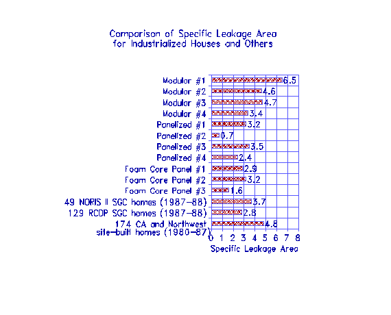
SLA is the only reference number shown which normalizes by floor area.
Figure 1 shows a comparison of SLA for all houses tested compared to houses
used for studies in the Northwest and California (Palmiter et al.,
1991).
Using a chemical smoke generator to pinpoint the cause of air leakage,
several common problem areas were evident. The highest occurrence of leaks
were found at:
- wall base plate and band joist areas;
- wiring and plumbing penetrations through floors and ceilings;
- recessed canister lights;
- building cavities used as part of the air distribution system (return
or supply plenums).
Duct Leakage and Pressure Balance
The last line in Table 1 gives the air leakage in the forced air distribution
system (duct system) at a reference pressure of 50 Pa (Duct Leak CFM50).
Based on research in Florida, it should be reasonable to get less than
100 CFM50 leakage in a duct system (Coyne, 1992). Of course, it
is possible to have zero leakage in a duct system but the accuracy of
diagnostic tools, and cost effectiveness criteria, may be limiting factors.
Of the eleven industrialized houses tested, only seven of them had a forced
air distribution system. Of those seven houses, three had less than 100
CFM50 duct leakage; two were stud-frame panelized houses and one was foam
core panel. Three modular houses had duct leakage between 121 and 742
CFM50.
Notable duct system leaks or other problems were found as follows:
- loose or unsealed duct-to-floor connections;
- taped seams instead of fiberglass mesh and mastic;
- interstitial building cavities used as return plenums;
- unsealed flex duct connections to rigid fiberglass boots or plenums
(use fiberglass mesh and mastic in addition to tie wraps)
- uninsulated metal connectors for flexible ducts--this could cause
condensation and energy loss problems;
In one stud-frame panelized house, additional infiltration testing was
conducted using SF6 tracer gas. One test was conducted with the air distribution
fan operating and resulted in an air infiltration rate of 0.68 air changes
per hour. A second test was conducted with the fan off and resulted in
an air infiltration rate of 0.36 air changes per hour. The difference
between these two results indicated that pressure induced air infiltration,
due to operation of the fan, increased the house air exchange rate by
89%.
Even if the entire air distribution system is within the conditioned
space, duct leakage and restricted return air flow paths can still cause
problems. Pressure imbalances can increase the house air infiltration
rate while the system fan is operating, and can cause portions of the
house to be uncomfortable. Pressure balance testing involves measuring
pressure differentials between the outdoors and the main body of the house,
and pressure differentials between closed rooms and the main body of the
house (Tooley et al., 1991). This type of testing is especially important
if there are combustion appliances in the house which do not have sealed
combustion chambers. The operation of any indoor natural draft combustion
equipment, that which relies on non-mechanical intake of inside air to
vent combustion products, can be seriously affected by negative pressures
created by air distribution and air exhaust systems. It is not uncommon
to find that the main body, basement, or utility room of a house can depressurize
to -3 to -6 Pa due to duct leakage, exhaust fans, and restricted air flow.
At these negative pressures, most natural draft equipment will show signs
of improper operation or failure, including back-drafting and flame roll-out.
The durability of materials used to construct a building can also be
affected by leakage in an air distribution system. For example, if supply
duct leaks are dominant in a house then the main body, where the largest
return usually is located, will depressurize. If that house is being cooled
in a humid climate, then moist air will be pulled into the walls and ceilings
possibly causing condensation on the back side of interior wallboard.
If, for example, the reverse is true, that is there are dominant return
leaks pressurizing the house while the house is being heated in a cold
climate, then moist air will be forced through walls and ceilings potentially
causing condensation on cold surfaces within the structure. Restricted
air flow from closed rooms to the main body will also cause pressurization
of the rooms.
The following list gives the more notable findings from the pressure
differential testing, along with possible solutions:
- Depressurization of the house main body to -8.5 Pa with the furnace
fan and kitchen and bath exhaust fans on, and the interior doors closed.
Presented potential problems with combustion safety, infiltration, and
comfort. Solution: Provide separate returns or transfer grilles to closable
rooms.
- Oversized return (or undersized supply) in bedroom causing the room
to depressurize to 4 Pa. Presented potential problem during humid cooling
season. Solutions: Properly size ducts, or add transfer grille.
- Return and supply duct leakage in basement. Presented potential problem
of combustion safety. Solution: Seal all return and supply ducts in
the basement.
- Three bedrooms in one house pressurized to between 8.5 and 11.5 Pa
with the furnace fan and exhaust fans on and interior doors closed.
Presented potential problems with wintertime condensation inside structure,
increased infiltration, and comfort. Solution: Provide separate returns
or transfer grilles to closable rooms.
- Clothes dryer could depressurize a relatively tight house to -3 Pa.
Presented a potential combustion safety problem. Solution: Provide make-up
air for the exhaust appliance.
- Basement depressurized to -6 Pa due to insufficient return air flow
area to the basement furnace fan. Presented potential problem with combustion
safety. Solutions: Increase return air flow to basement; provide vents
for combustion and dilution air per National Fire Protection Agency
Code NFPA 54 for Confined Spaces.
Infrared Imaging
Through infrared imaging, irregularities and defects in the thermal envelop
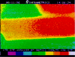
of the house were detected. Figure 2 shows how ceiling insulation was
completely missing over part of a second floor bedroom and stairwell in
a modular house.
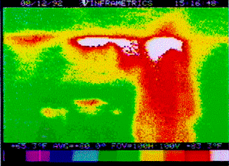
Air leaks in marriage walls of modular houses may be common but are easily
corrected with foam sill sealer, high quality caulk, or polyurethane foam
when pulling the units together (Pudget, 1991). Figure 3 illustrates how
hot attic air was leaking into a marriage wall, short circuiting the thermal
envelope.
Thermal shorts in walls can be especially obvious when comparing the
thermal image of a stud framed wall and a foam core panel wall. This is
illustrated in Figure 4.(a) and (b). The more conductive wood framing
shows up as a cold area, potentially allowing moisture problems to develop
in exceptionally cold climates.
insert figures 4(a) and 4(b)
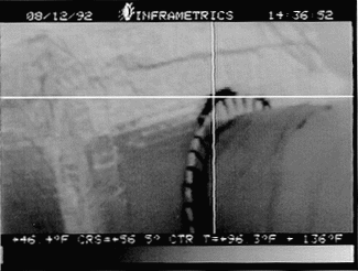
Energy loss due to duct leakage can be a significant factor in residential
energy use. In a study in Florida (Cummings et al., 1991), the
average percent reduction in energy use by repairing leaky ducts was 17%.
Figure 5 shows an example of duct leakage, which was found by infrared
imaging, in one of the modular houses tested. It shows 56oF air leaking
out of a duct located in a hot attic.
Other common findings using infrared imaging include:
- Convective heat flow where ceiling insulation was bulged up near the
eaves allowing air movement between the insulation and the wallboard;
- Conduction heat flow where ceiling insulation was not full thickness
at the eves;
- Heat flow due to air leakage through tongue and grooved wood ceilings;
- Air leakage between the finished floor and the baseboard due to insufficient
air tightening of the wall base plate and band joist area;
- Air leakage from the exterior through framing cavities connected to
return air plenums which were not air sealed;
- Air leakage from the exterior through unsealed interior soffits and
spaces behind cabinets;
- Improperly insulated knee walls;
- By-pass of insulation due to air leakage through recessed ceiling
lights;
- Air leakage through electrical wiring penetrations, especially where
insulation was compressed behind wiring;
Conclusions
To our knowledge, this is the first time data has been reported on air-tightness
and thermal insulation quality of modular, stud-frame panelized, and foam
core panel housing in the U.S.A. The limited data indicates that panelized
and foam core houses are being constructed with better air-tightness compared
to conventional site-built houses. It seems that modular homes do not
yet attain the full potential of greater energy efficiency possible with
factory construction. The tests pinpointed the energy loss areas both
visually and through measurements, demonstrating the room for improvement
to the manufacturers. As a result, some have made changes or are in the
process of making changes which when multiplied many times over in the
factory environment can have a substantial impact on the quality of houses
being constructed today.
Future Work
A side-by-side study of a foam core panel house and a conventional stick-frame
house is currently being conducted to further quantify the performance
difference between conventional and industrialized housing. After collecting
construction and cost data, air-tightness and thermal insulation quality
testing will be conducted, followed by short-term energy use monitoring.
References
ASHRAE, 1989. ASHRAE Standard 62-1989. American Society of Heating, Refrigeration
and Air-conditioning Engineers, Atlanta, GA.
Coyne, Brian, 1992. "A Million Miles of Ducts: Duct Sealing Update."
Home Energy, March/April.
Cummings, James B., John Tooley, Neil Moyer, 1992. "Duct Doctoring:
Diagnosis and Repair of Duct System Leaks." Under contract to Florida
Energy Office. Florida Solar Energy Center, January.
Judkoff, Ronald D., Gregory M. Barker, 1992. "Thermal Testing of
the Proposed HUD Energy Efficiency Standard for New Manufactured Homes."
National Renewable Energy Laboratory, NREL/TP-253-4490, June.
Meir, Alan, 1986. "Infiltration: Just ACH50 Divided by 20?"
Energy Auditor & Retrofitter, July/August.
Palmiter, L.S., I.A. Brown, T.C. Bond, 1991. "Measured Infiltration
and Ventilation in 472 All-Electric Homes." ASHRAE Transactions,
Volume 97, Part 2.
Pudget Sound Power & Light Company, 1991. "Details: Marriage
Line Sealing in Manufactured Homes." Bellevue, WA.
Tooley, John J., James B. Cummings, Neil A. Moyer, 1991. "Pressure
Differential 'The Measurement Of A New Decade'," Proceedings of the
Ninth Annual International Energy Efficient Building Conference, Indianapolis,
IN, March.
Tsongas, G., 1992. "A Field Study of Indoor Moisture Problems and
Damage in New Northwest Homes." Proceedings of the ASHRAE/DOE/BTECC
Conference, Clearwater Beach, FL, December.
Tsongas, George A., Joseph Lstiburek, 1992. "Indoor Air Quality
Residential Issues Workshop Notebook." Presented at Thermal Performance
of the Exterior Envelopes of Buildings V, Clearwater Beach, FL, December.
Wahlstedt, D., 1991. "Residential Ventilation Control." Final
Report, 1990 Joint R/BC-SSDC Project. Honeywell Inc., Minneapolis, MN.


