Case Study:
High Efficiency Florida Home
Longwood, Florida
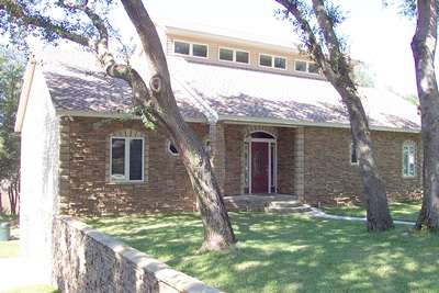 |
Figure 1. 4,200
sq. ft., 3-story home located in Longwood, Florida |
This three-story, 4,250 square foot home was completed in February 2001 by Mr. David Hoak in Longwood, Florida near Orlando. FSEC assisted by recommending a package of features to produce an exceptionally energy efficient design at a reasonable cost. The building envelope design and mechanical equipment selection were intended to work together as a system. As a result the home can be cooled with a much smaller air conditioner than is needed by most homes of this size in the hot and humid Florida climate.
| A datalogger was installed in late April 2001 and data collection is ongoing. See a summary of current data at the InfoMonitors web site. A detailed data interface is also available where graphs can be produce like those used in the case study below. |  |
Envelope Features
High Performance Windows
Roughly 25% of the annual cooling load in a typical Central Florida home is introduced through the windows. Recent advances in window technology allow this load to be greatly reduced.
The windows used here are particularly useful in Florida for two reasons: (1) very low Solar Heat Gain Coefficient (SHGC) to reduce direct solar gains and (2) relatively high Visible Transmittance (VT) for natural daylighting. These ratings were determined in accordance with National Fenestration Rating Council (NFRC) procedures.
NFRC
ratings |
|
U-
value |
0.28 |
SHGC |
0.31 |
VT |
0.51 |
The bar chart below shows the impact of the window upgrade over a typical, minimum code, single-pane clear glass installation. The upgraded windows reduced the peak cooling load by nearly one ton (10.6 kBtu/hr). Other improvements like tightening the building envelope, reducing duct leakage and moving the ducts out of the hot attic reduced the cooling load even further.
Unvented Attic
Most Florida homes have vented attics with batt or blown insulation applied just above the ceiling. This exposes air conditioning ductwork to very high temperatures and further magnifies any problems associated with duct leakage. Sealing the attic envelope and insulating at the roof deck (as seen in Figure 2) provides a semi-conditioned space for the ductwork, reducing conductive heat gain and minimizing the detrimental impact of any duct leakage.
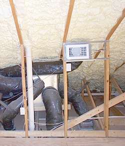 |
Figure 2. Foam
insulation applied at roof deck |
Expanding Foam Insulation
A layer of expanding foam insulation was applied to the underside of the roof deck to create an unvented, semi-conditioned attic (R-22). The same insulation was applied to all above-grade walls (R-11). While the insulation R-values were standard, the primary benefit comes from a nearly airtight seal provided by the foam, greatly reducing infiltration of outside air.
Continuous Air Barrier
Infiltration of Florida's hot and humid outside air can
have a major impact on energy use, as well as building durability
and occupant health. A continuous air barrier was installed
around the building to reduce infiltration. Indoor air quality
concerns were addressed with
an energy recovery ventilator
to introduce outside air.
The barrier consisted of a house wrap product installed over the exterior sheathing on all above-grade frame walls and tightly taped, extruded polyurethane foam boards glued to the interior of all below-grade block walls. Expanding foam insulation provided an extra measure of airtightness at all above grade exterior surfaces including the roof deck. Special care was taken to seal wall details such as corners, floor interfaces and the roof junction. Blower door performance tests verified the level of airtightness (ACH50 = 2.0).
Equipment Features2-Speed, Zoned Heat Pump
The building envelope design features described above greatly reduced the required air conditioner size. Manual-J HVAC equipment-sizing calculations showed the need for about 3.0-tons of heating and cooling capacity. In this case the owner opted for a two-speed compressor, which provides either 3.0 or 5-tons of cooling or heating depending on the need.
 |
||||||||||||||||||||||
Air
conditioner energy use on a typical hot day |
||||||||||||||||||||||
|
||||||||||||||||||||||
The figure at left shows air conditioner operation on a typical hot day (Aug 24, 2001). The unit ran in the 3.0-ton mode until the late afternoon when it switched to the 5-ton mode for a few brief periods. In this case we have the best of both worlds: energy use is kept low by primarily using the low compressor speed, but when quick cool-down or excessive loads are encountered the high speed is there to meet the need. Measured data indicated the 5-ton mode was used about one in every four days over the three hottest summer months (June - August), usually for periods of 15 minutes or less, and even these short periods of high-speed compressor operation could likely be avoided with proper use of a programmable thermostat. These results verify the Manual J sizing calculations and indicate that if a single speed HVAC system were installed, the optimum size would be 3.0-tons.
HVAC
System Efficiency |
|
Cooling |
Heating |
SEER
13.35 |
HSPF
7.5 |
Variable-speed Air Handler
 |
||||||||||
Indoor
relative humidity tends to increase with a less active
air conditioner |
||||||||||
|
||||||||||
Two benefits of using a variable-speed motor for air distribution are better dehumidification and energy efficiency. During the cooling season, slower airflow across a cold coil allows for more moisture removal, which is achieved here by gradually increasing the motor speed and holding it at 80% of maximum. Wintertime comfort is also enhanced since the coil has more time to warm up before the air is brought to full flow.
A graph of indoor relative humidity (RH) and air conditioner activity (at right) shows how RH tends to increase during the fall and winter months when AC activity tends to drop off. Without a dedicated dehumidifier, the air conditioner is the only means of reducing indoor RH. Here the low-speed (3.0-ton) compressor is able to operate more consistently than a larger system normally would and, in conjunction with the variable speed air handler, RH is kept from rising to unhealthy levels.
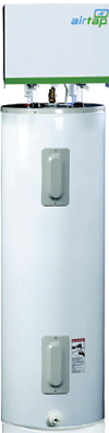 |
Figure 3. Heat pump water heater installation |
Heat Pump Water Heater
Solar water heating would have been the first choice for this home but poor orientation and too many shade trees caused a search for other options. Natural gas was also not available. To avoid the inefficiency of electric resistance heating, a 6,000 Btu/Hr heat pump water heater was connected to a standard 80-gallon electric water heater. By locating the heat pump inside the home, a summertime benefit of an additional 1/3-ton of cooling and dehumidification was gained from the output of the heat pump each time it operated.
The control scheme was designed to minimize use of the electric elements, reserving them for backup heating when the heat pump failed to meet demand. The heat pump essentially replaces the function of the lower element in the electric water heater. Data collected from April to September of 2001 showed the unit produced all the hot water needs for a four-person household without using electric backup heating.
A problem that was later corrected caused the heat pump to shut down midway through September and offered a chance to compare heat pump and electric resistance water heating performance. During the first 13 days of September the heat pump used 32.7 kWh, while 86.2 kWh was consumed during the following 13 days when hot water was supplied solely by electric resistance. Although hot water use was not monitored during this period to ensure a fair comparison, the graph below illustrates the improved efficiency.
 |
||||||||||
Energy
use increased after heat pump shut down - Sep 13 |
||||||||||
|
||||||||||
Energy Recovery Ventilator
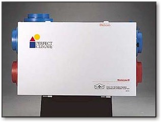 |
Figure 4. Energy recovery ventilator provides outdoor air to home |
An energy recovery ventilator acts as a conduit to flush out stale indoor air and replace it with outdoor air. As the indoor air is expelled, a heat exchanger recovers up to 80% of the energy used to heat or cool the indoor air. In turn, the recovered energy is transferred and used to heat or cool the incoming stream of outdoor air. This particular unit also transfers a portion of the moisture between the airstreams, which is useful during periods of high outdoor humidity.
Airtight Ducts
Attic and duct gains make up about 22% of the cooling needs in a typical Central Florida home. This is for a home with ducts located in a vented attic above the insulation. While some efficiency is lost by direct heat-gain through the duct insulation, which is typically R-6, a great deal more efficiency can be lost from unintended leakage of supply and return ductwork into the vented attic. Duct leakage test results showed only 50 cfm of air was lost at 25 Pa of pressure differential with respect to the outside of the home, or 1.2% leakage per square foot of conditioned floor area - far below the number normally found in new Florida homes.