Return Air Pathway Study
Scope
In effect since March 2003, Section 601.4 of the Florida Building Code applies to residential and commercial buildings having interior doors and one, centrally located return air intake per heating and cooling system.
Objective Of The New Florida HVAC Code Requirement
Reduce pressure difference in closed rooms with respect to (wrt) the space where the central return is located to 0.01” water column (wc) or 2.5 pascal (Pa) or less. Pressure imbalances created by restricted return air flow from rooms isolated from the central return by closed interior doors create uncontrolled air flow patterns.
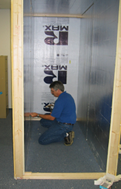 |
Figure 95. Return Air Flow Test Chamber |
Technical Background
Ideally, forced-air heating and cooling systems circulate an equal volume of return air and supply air through the conditioning system, keeping air pressure throughout the building neutral. Each conditioned space in the building should, ideally, be at neutral air pressure at all times.
When a space is under a positive air pressure, indoor air will be pushed outward in the walls, floor and ceiling. When a space is under a negative pressure, air will be pulled inward through the walls, floor and ceiling. Negative and positive air pressures in buildings result from uncontrolled air flow patterns.
Section 601.4 of the Florida Building Code specifically deals with the uncontrolled air flow pattern when interior doors are closed thereby reducing return air flow from the closed room, while maintaining the same supply air flow to the room. This imbalance of supply and return air has been addressed conventionally by the common practice of undercutting interior doors to allow return air to flow from the room. This research quantifies the volume of air flow provided by this and other methods of return air egress from closed rooms.
Section 601.4 limits the air pressure imbalance in closed rooms to 0.01” wc or 2.5 pascals when compared to, or with respect to (wrt), the main body of the building where the return is located. With door undercuts, researchers have regularly observed room pressures with respect to the main body of the house (wrtmainbody) of +7 pascals (pa) or more. A room with this level of air pressure (+7pa, wrtmainbody) is trapping air, starving the heating/cooling system of return air. As the heating/cooling system struggles to pull in the designed amount of air, the resulting negative pressure pulls air into the main body of the building along the path(s) of least resistance. Usually this means that air is flowing through the walls, floor and ceiling from unconditioned spaces or outside environment to makeup for the trapped air in the closed room.
In the closed room, positive pressure builds up when return air is trapped. Conversely, the space with the central return gets depressurized because extra return air is being removed to make up for the air trapped in the closed room. More air is leaving the space (return air) than is entering the space (supply air). The positive pressure in the closed rooms pushes air into unconditioned spaces, such as the attic and wall cavities. The negative pressure in the main body of the building pulls air from unconditioned spaces. In Florida, the air brings heat and moisture with it that become an extra cooling load. This air is referred to as “mechanically induced infiltration” since the negative pressure drawing infiltration air in was created by the mechanical system.
Styles of Pressure Relief
When return air flow is restricted by closed doors, it creates pressure differences between parts of the building. This can be prevented by installing a fully ducted return system, by creating a passive return air pathway such as a louvered transoms, door undercut, “jump duct”, through-wall grilles, or a baffled through-wall grill.
A “jump duct” is simply a piece of flex duct attached to a ceiling register in the closed room and another ceiling register in the main body of the house. A jumper duct provides some noise control while providing a clear air flow path.
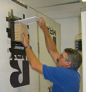 |
Figure
96. Installing sound baffled return air flow through wall
insert made by Tamarack. |
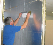 |
Figure
97. Installing unbaffled return air flow through wall grille. |
A through-wall grille is the simplest and least expensive approach to pressure relief for closed rooms. Holes opposite each other on either side of the wall within the same stud bay are covered with a return air grilles. The downside of this approach is a severe compromise the privacy of the closed room. An improvement on this theme would be to locate one of the grilles high on the wall and the opposing opening low on the wall. Also, such openings in interior wall cavities introduce conditioned air into what is typically an unconditioned space possibly contributing to other building problems.
However, connecting the two openings with a sleeve of rigid ducting forms an enclosed air flow path that limits introduction of conditioned air into the wall cavity but doesn’t solve the visual and sound privacy issues. To address this problem, BAIHP Industry Partner Tamarack developed a sleeve with a baffle that can reduce the transfer of light and sound but still provide adequate air flow to minimize pressure differences. The product is called a Return Air Path (RAP).
To validate the effectiveness of this product and other approaches to providing return air pathways, Tamarack and BAIHP researchers devised a test apparatus and conducted experiments in FSEC’s Building Science Laboratory.
Testing Protocol
In May of 2003, a chamber was constructed at FSEC (Figures 95-98) that simulated a frame construction room with an 8 foot high ceiling. A “Minneapolis Duct Blaster” was connected to one end of the room with a flexible duct connection leading out of the room to provide control over pressure in test chamber.
In the middle of the chamber, on a stool, a radio was tuned “off station” to effectively create a standardized level of “white noise” at 57 dBA inside the chamber with the “door” closed. The temperature at the start of the tests was 80°F at 40%RH. A sound meter was located outside the chamber on a stand 4 feet above the floor and 20 inches from the middle of the chamber wall surface.
The sound level in the test facility outside the chamber with the “white noise” turned off was 36.4 dBA and with the “white noise” turned on was 41.5 dBA, an average, sampled over a 30 second period. A series of tests on 31 different set-ups were performed, measuring the flow at 3 different pressure levels and recording a 30 second sound sample with the “Duct Blaster” deactivated.
Tests were made for 6” and 8” jump ducts, five different sized wall openings (Figure 97) in different configurations including straight through with and without sleeves, straight through with sleeve and privacy baffle (Figure 96), and high/low offset using the wall cavity as a duct, and three different slots simulating three different size undercut doors.
Results
Table 60 summarizes the results of these tests arranged in ascending air flow order based on the results at 2.5 Pascals (0.01” wc), the maximum allowable pressure in a closed room under new requirement in Florida Building Code, Section 601.4.
Table 60 Air
Flow Resulting from Various Return Air Path Configurations
at Controlled Room Pressure Difference (ΔP) with respect to Return Zone
Dim. |
Air Flow (cfm) at |
Area |
Air
Flow to |
Return
Air Path |
Extra |
||
ΔP= |
ΔP= |
ΔP= |
|||||
6 dia |
22 |
36 |
52 |
28 |
1.29 |
Jumper Duct |
|
4x12 |
26 |
41 |
60 |
48 |
0.85 |
Wall Cavity |
|
4x12 |
25 |
42 |
61 |
48 |
0.88 |
Wall Sleeve |
RAP Insert |
4x12 |
28 |
45 |
65 |
48 |
0.94 |
No Sleeve |
|
4x12 |
29 |
46 |
68 |
48 |
0.96 |
Wall Sleeve |
|
8x8 |
31 |
49 |
72 |
64 |
0.77 |
Wall Cavity |
|
12x6 |
32 |
52 |
75 |
72 |
0.72 |
Wall Cavity |
|
12x6 |
33 |
56 |
82 |
72 |
0.78 |
Wall Sleeve |
RAP Insert |
8x8 |
35 |
57 |
81 |
64 |
0.89 |
No Sleeve |
|
8x8 |
34 |
58 |
83 |
64 |
0.91 |
Wall Sleeve |
RAP Insert |
8x8 |
36 |
59 |
85 |
64 |
0.92 |
Wall Sleeve |
|
12x6 |
36 |
60 |
88 |
72 |
0.83 |
No Sleeve |
|
12x6 |
37 |
60 |
88 |
72 |
0.83 |
Wall Sleeve |
|
1 x 30 |
39 |
61 |
88 |
30 |
2.03 |
Slot |
|
8 dia |
38 |
62 |
90 |
50 |
1.24 |
Jumper Duct |
|
1 x 32 |
42 |
65 |
92 |
32 |
2.03 |
Slot |
|
8x8 |
40 |
67 |
95 |
64 |
1.05 |
Wall Cavity |
Two Inside Holes |
8x14 |
44 |
70 |
100 |
112 |
0.63 |
Wall Cavity |
|
12x12 |
45 |
72 |
103 |
144 |
0.50 |
Wall Cavity |
|
1 x 36 |
49 |
73 |
103 |
36 |
2.03 |
Slot |
|
8x14 |
61 |
101 |
146 |
112 |
0.90 |
Wall Sleeve |
RAP Insert |
8x14 |
68 |
107 |
153 |
112 |
0.96 |
No Sleeve |
|
8x14 |
68 |
110 |
154 |
112 |
0.98 |
Wall Sleeve |
|
12x12 |
75 |
119 |
170 |
144 |
0.83 |
No Sleeve |
|
12x12 |
74 |
120 |
169 |
144 |
0.83 |
Wall Sleeve |
|
12x12 |
74 |
120 |
174 |
144 |
0.83 |
Wall Sleeve |
RAP Insert |
By comparing the air flow of the slots (door undercut) to the openings with grilles, the detrimental effect of the grille becomes clear. The ratio of air flow (cfm) to the surface area of the slot (in2) is more than 2 to 1 (for example; 30 in2 to 61 cfm), whereas with grilles in place the ratio of air flow to area averages 0.83 to 1 (for example; 72 in2 to 60 cfm). Similarly, the jump duct (Figure 98) assemblies’ air flow to area ratios average 1.19 to 1. In any calculation for the size of the through wall assembly, the resistance of the grille becomes the critical factor in determining the size of the opening for achieving the desired flow.
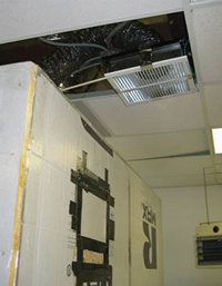 |
Figure
98. Return air flow path provided by jumper duct. |
The following formulas account for the grille resistance and maybe used to size return air path openings.
- Door undercuts: Area Sq. In. = CFM/2
- Wall opening with grilles: Area Sq. In. = CFM/.83
- Flexible jumper duct with grilles: Diameter =

Although there does not appear to be significant flow improvement when a sleeve is used, such an assembly will reduce the possibility of inadvertent air flow from the wall cavity itself.
The high/low grilles using the wall cavity reach maximum flow at 72 cfm because of the dimensional limitations of the wall cavity itself. Increasing the opening of each grille beyond 112 square inches does not significantly increase the flow of air through the wall cavity.
The accompanying bar chart (Figure 99) can be used to select the best method at various air flows while maintaining the room-to-building pressure difference at .01” wc. The strategies are ranked by air flow allowance (cfm) on equivalent to supply air delivered to the room. For example, an 8” jumper duct could be used to maintain 0.01 wc in rooms with supply air up to 60 cfm. Note that these transfer methods are additive so that, for example, combining a 6” transfer duct with a 1” undercut a 30” door, will provide a flow of 95 cfm to be delivered at .01” wc (Figure 99) or combining a R.A.P. 12.12 with a 1” undercut would allow up to 175 cfm to be delivered . It should be noted that door undercuts are under builder not HVAC control and that the actual dimensions are greatly affected by the thickness of the floor coverings.
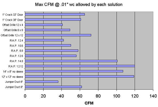
Figure
99. Maximum air flow achievable using various
return air paths from closed rooms for a
give
supply at a room pressure
of 2.5 pa or 0.1" wc with respect to the return zone. For example,
an
8" jumper duct could be used to maintain 0.01 wc in rooms with supply
air up to 60 cfm.
Summary
Ideally buildings with forced air heating/cooling systems are pressure neutral. The same amount of air is removed from the building (and each room) as is supplied to it. However, this balance can be disturbed in homes that have one, centrally located return intake when interior doors are closed, blocking return of air supplied to private rooms. Other factors outside the scope of this study may also result in household pressure imbalances.
These research results are relevant to homes with forced air heating and cooling systems having a single, centrally located return air inlet with no engineered path for return air to exit closed rooms. Such systems pull return air from the whole house as long as interior doors are open. When an interior door is closed, more air is supplied to the closed room than can be removed, or returned, from the room.
Positive pressure builds up in the closed room while a negative pressure occurs in the connected spaces. Positive pressure presses outward on all surfaces and may eventually reduce supply air flow into the closed room and while pushing conditioned air through small breaks in the room’s air barrier.